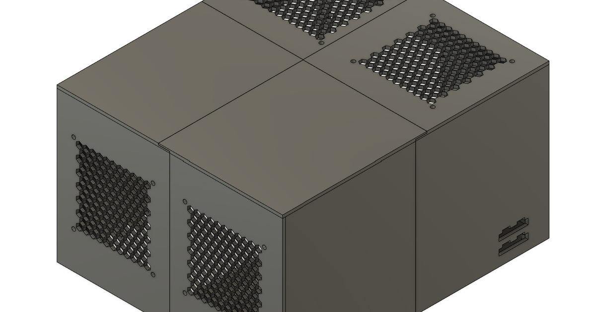
JBOD v2 - Enclosure for 16 Drives (JBOD/HBA)
JBOD v2 - Enclosure for 16 Drives (JBOD/HBA)


Print Profile(2)


Description
Please rate!
I ran out of physical space to add more hard drives to my home server. Given that I already had a few parts laying around, I didn't want to spend several hundred dollars on a prebuilt enclosure. So, I set out to make my own.
BOM:
- This SAS SFF-8088 to SFF-8087 converter
- This SFF-8087 to SATA cable.
- This SFF-8088 cable.
- An HBA card for the server.
- I'm using an LSI 9200-8e as I only have 8 drives going and started this as a proof of concept.
- A good list of cards can be found here. You'll want an external card with SFF-8088 ports if following this build guide.
- An ATX power supply. The mount points are spec'd to the spec.
- The cutout for the intake fan of the PSU is 149x139 and is offset by 5.5mm from the edges (see reference photo).
- I'm using a beQuiet! Straight Power 11.
- Four M2xH4 heated inserts.
- These nylon standoffs if you are using more than one adapter card.
- 120mm 12V fans.
- I'm using the Noctua NF-P12 due to their low noise at full speed.
- Has mounting for up to six fans.
- (Optional) A fan power hub
- I'm using a Corsair power hub that I had laying around, but something like either of these two should work.
- Alternatively, there are plenty of options for using adapters/splitters to power the fans directly off the PSU.
Printing:
I printed everything with 4 walls and 60% gyroid infill (this required about 3 kg of filament). You can probably get away with less infill for the panels, but I'd still recommend printing the base and tenons on the denser side. I used PLA as a thermal camera showed the hottest drive sitting under 40*C.
The model file has a user parameter for joint clearance if you need to dial it in. The tenons can be scaled.
You will need 26 tenons.
Assembly:
All pieces are held together by interference fit joinery, so no gluing is required. The tenon joints might need a slight tap from something mildly heavy to help them close. I used a 4 oz hammer, but the backside of a screwdriver should get the job done just as well. Assembly should be relatively straight forward, but it is critical to double-check the orientation of each piece before popping the joints together.
- Join the bottom pieces first.
- Join the two back panels and attach to the bottom.
- Join the panels for each side and then attach to the bottom and the back panels.
- Join the panels for the front and then attach to the bottom and side panels.
- Join the panels for the top together.
- Install the adapter card by putting it level with the external opening and pushing in. The holes should line up with the standoffs that are printed on the bottom panel.
- Install 15 mm long standoffs if adding a second card.
- Secure the top card with screws. Anything 6 mm long and shorter should work.
- Install the HDDs.
- The shim is to account for slight variations in the HDD slots when printing. The thickness can be adjusted by changing the layer height in your slicer. The idea is to slide this in with the hard drive to take out an side-to-side wobble. Depending on your drives, this may not be necessary.
- Install the PSU and secure it in place using the normal mounting screw points.
- Install the fans.
- Install all cabling and make sure the cables are free of the top fans.
You'll have to decide how you want to handle powering the PSU as there are a number of options. Some examples:
- I have a modular PSU, so I ground the PS_ON pin directly on the PSU.
- Use a jumper plug
- Install a switch or latching button