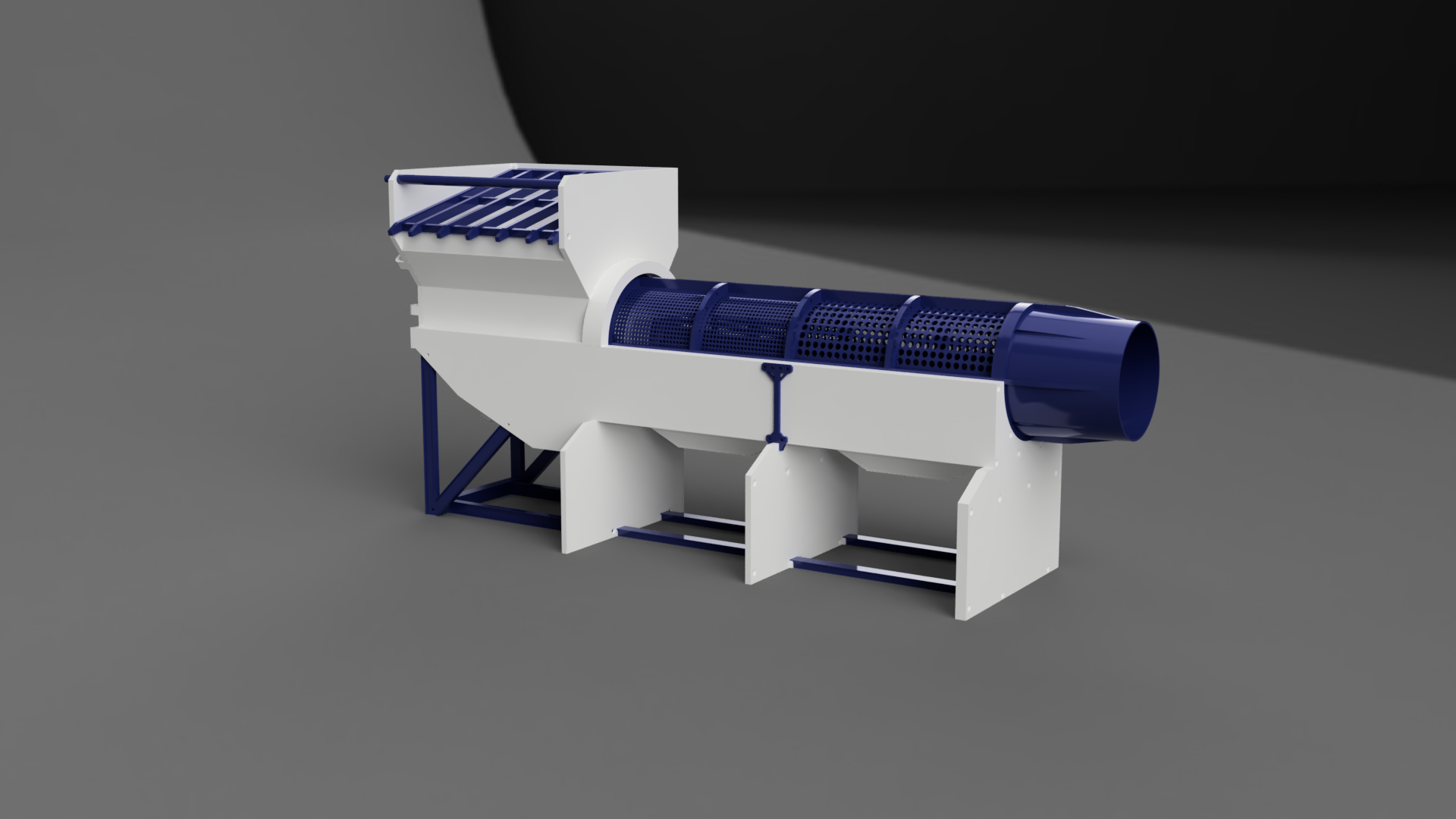
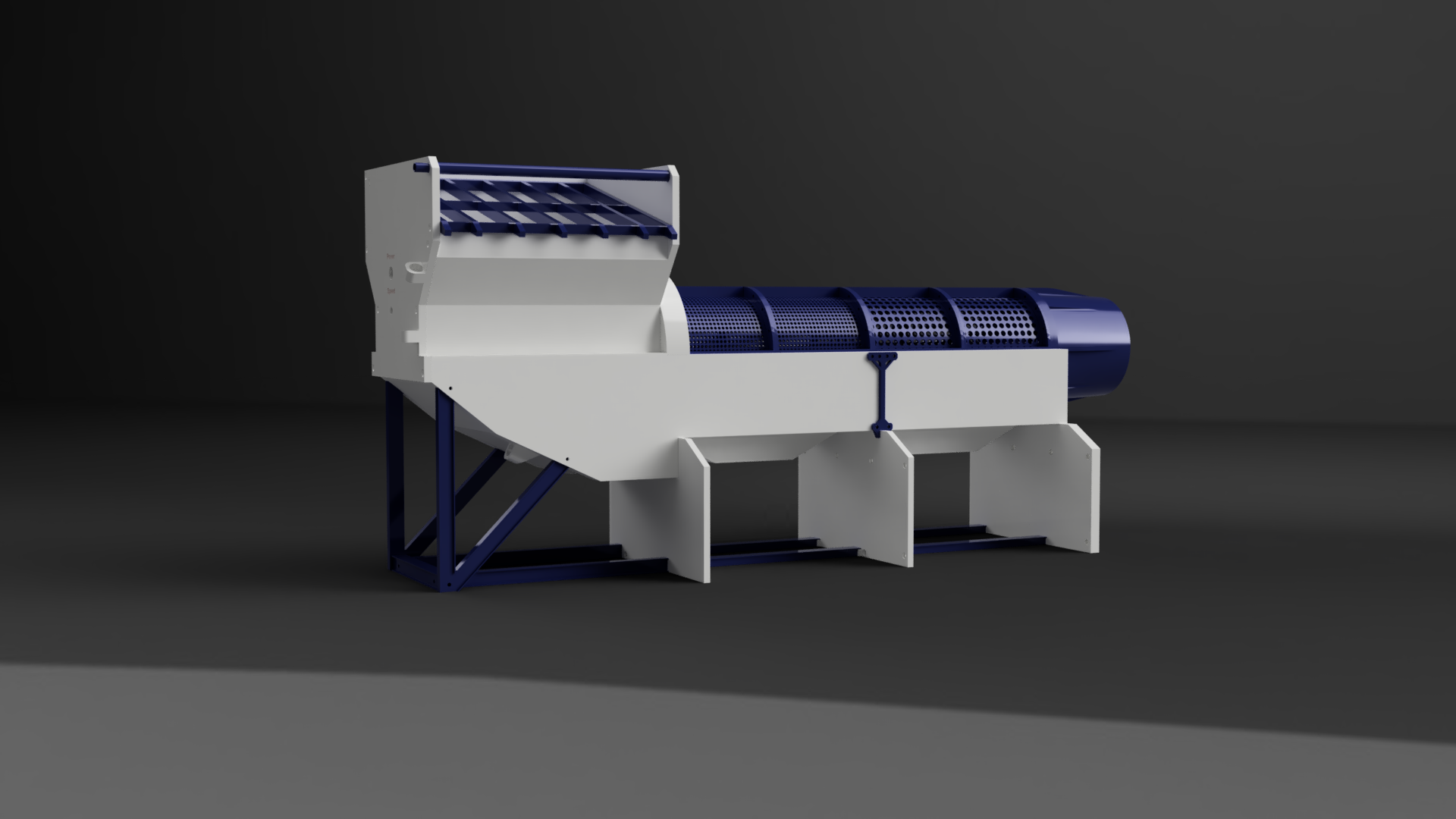
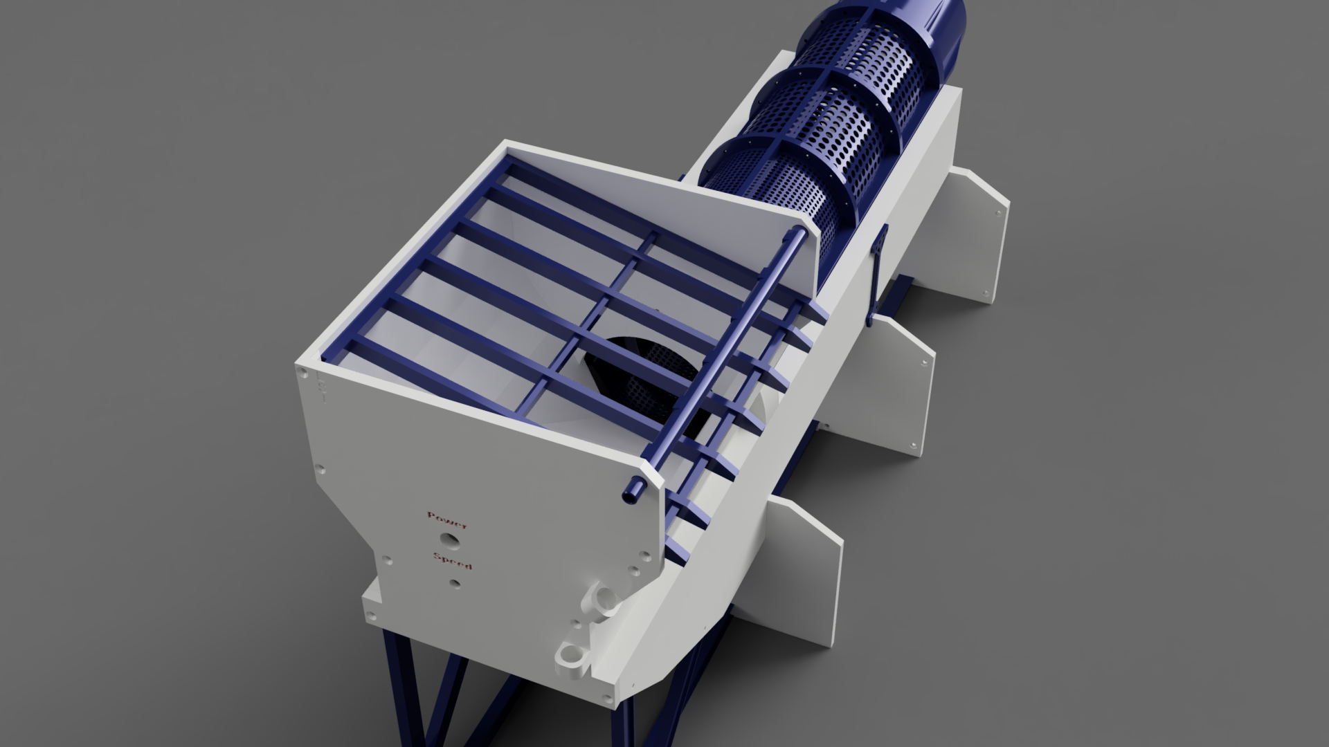
This is a 1/16 trommel that I redesigned. It's meant to be run by a 12v battery. This model can use a small aquarium pump to add water through a spray bar. You'll get all the files and the fusion file to look at for ease of assembly and modification. In the fusion file are also gold sluices and mats that are 3d printable.
ASSEMBLY -
Part 1 - Place the 'Left and Right Middle support w/ Chute' together with 5 countersunk 8mm screws and 5 nuts. Then an additional 2 8mm button head screws and 2 nuts in the access hole. Then attach the connecting plates on the seems with 12 8mm button head screws on both sides.
Part 2 - Grab 'End Support 1 and 2'. Then 2 of the bearings. You will need 2 12mm countersunk screws to hold the bearings in between the two supports and screw into the Right Chute. They should come out on the other side of the chute and you'll use two nuts to secure. Once the bearings are in place, use 6 16mm countersunk screws to secure the chute. Afterward, use 5 10mm countersunk screws to connect the supports at the bottom. The order should be right chute, end support 2, bearing, then end support 1.
Part 3 - You'll need to grab the 'front bearing mount', 'motor mount plate', and the motor. Use 6 12mm button head screws to attach the motor to the bearing mount and the plate. The order should be, Bearing mount, plate, and then motor. Once the motor is attached, lay your flange loosely on the bearing mount, it only fits one way, and the inside lip should fit slightly loose. Once in place, use 3 10mm button head screws to attach the 3 bearings on the bearing mounts (the 3 pieces that stick up off the surface).
Part 4 - The next step is putting the 'modified Pinion gear' on the motor. It should barely not touch the flange. to keep it in place, use a 10mm m2 set screw. Next, you'll need the 'Front support structure'. The entire motor and flange assembly should slide into the front support structure, it's keyed to fit only one way. Once in place grab the rest of your assembly (Middle support chutes, and end support) and place it next to the Front support structure. Grab 6 25-30mm button head screws, and place them through the 6 locations inside the front support structure, they will extend and connect to the left support chute.
Part 5 - After you have your whole support structure built. You need to assemble the actual trommel. Start with the '3mm trommel P1' that has screws going into the 4 supports. (its end will have screws that look apart from the others). Once you find the end that looks different, keep that side facing to your left. Then attach the '3mm Trommel P2' on the right by lining up the agitator bars and the spirals. Use at least 4 8mm button head screws with nuts to connect. Then grab '6mm Trommel P3' and repeat the same process, same for '6mm Trommel P4'.(These really can only go one way). Lastly, connect the 'End of trommel P5' with 4 16mm m3 screws and nuts.
Part 6 - Now that you have your entire trommel assembly, you'll need the 'Modified Ring gear'. Place the ring gear on the gear and flange assembly, and let it rest. Then bring your trommel assembly and place it on the support structure. Grab 8 16mm countersunk screws with 4 nuts, align the gear and trommel so that you can place screws through the flange to the trommel. Get as many screws as you can for now, until you can turn the motor on. (or if you are able to spin the motor to do it now it's okay)
Part 7 - To start wiring grab the 'front plate' one switch, and the 12v dc motor controller. The 12v Dc controller has labels on the bottom for where to run wires. Grab your cable, attach the red wire to the positive on the controller and the black to the negative, and cut the wire about 6 inches long. Then take the red wire and run it to one of the poles on the switch. Now you're ready to make a battery cable, depending on how far you want to place your battery away. But to make the battery cable take the red wire and run it to the empty pole on the switch, and connect the black wire to the one you cut earlier that runs to the controller. Next, connect the motor to the dc controller. Before testing the motor, connect the potentiometer to the dc controller, and turn it full counterclockwise. Now you can test which way your motor is spinning by hooking it up to a battery. Connect your battery and slowly start turning the potentiometer a little bit, and flicking the switch. Once it spins a little I recommend putting the rest of the screws in. If it is spinning in the correct direction. You can mount everything to the backside of the front plate. If not just switch the polarity to the motor on the dc controller.
Part 8 - Grab the 'Hopper Feed' and place it on top of the front support structure. It will notch into the motor mount plate. Then grab 2 10mm countersunk screws to connect it to the motor mount plate. Then optionally if you want the spray bar and grizzly bar, place those in their respective holes, and finally attach the front plate, making sure to line up the grizzly bar and spray bar. Use 8 10mm countersunk screws to attach the front plate to the entire structure. Then, for good measure, there is 1 more countersunk 10mm on the opposite side of the grizzly bars.
Part 9 - Finally you can assemble the Support Beams. These are kinda optional but help with rigidity a lot if you'll be moving it a bunch. The 'right beam x2' goes under the right chute, and the left goes under the left chute. They use 8mm countersunk screws. 'Support Beam left' and 'Support beam right' attach to the 'front support structure' from underneath, and have screws on the side. Use 4 10mm button head screws. Once the Support beams right and left are attached, grab the 'Support Beam Middle x1' and it should slot into the other beams you attached using 2 8mm button head screws. Then grab the 'Support beam to the front structure x2' and connect that to the middle support and the front support structure with 2 8mm countersunk screws, and another 2 8mm button head screws.
The parts list is..
M3 countersunk screws- https://a.co/d/4TAhyW3
M3 button head screws- https://a.co/d/4TAhyW3
(need at least 6 30mm button head screws)
7 3x10x4mm Bearings (10 pack on aliexpress for $5)-
https://www.aliexpress.us/item/3256804036834674.html?spm=a2g0o.order_detail.order_detail_item.3.7849f19cMMuZky&gatewayAdapt=glo2usa
12v 100rpm 37mm motor with a D shaft - https://www.aliexpress.us/item/3256803614769941.html?spm=a2g0o.order_list.order_list_main.16.66541802lshEwJ&gatewayAdapt=glo2usa
12v Dc motor controller - https://www.aliexpress.us/item/3256803614769941.html?spm=a2g0o.order_list.order_list_main.16.66541802lshEwJ&gatewayAdapt=glo2usa
Wire - https://a.co/d/2RoQJb1
Switch for motor - https://www.aliexpress.us/item/3256805689677106.html?spm=a2g0o.order_list.order_list_main.11.66541802lshEwJ&gatewayAdapt=glo2usa
Spray Bar aquarium pump (any should work as long as it fits ID 5/16 hose) - https://a.co/d/bGq89jd
ID 5/16 OD 7/16 in tube for Spray Bar - https://a.co/d/1FdMDfs
M2 10mm set screw -
https://www.aliexpress.us/item/3256802982552374.html?spm=a2g0o.detail.pcDetailTopMoreOtherSeller.4.754c6e83hDohfF&gps-id=pcDetailTopMoreOtherSeller&scm=1007.40000.327270.0&scm_id=1007.40000.327270.0&scm-url=1007.40000.327270.0&pvid=0868aa27-d8d5-49b8-8523-7aee46eb911a&_t=gps-id:pcDetailTopMoreOtherSeller,scm-url:1007.40000.327270.0,pvid:0868aa27-d8d5-49b8-8523-7aee46eb911a,tpp_buckets:668%232846%238109%231935&pdp_npi=4%40dis%21USD%210.66%210.43%21%21%210.66%210.43%21%4021032dcb17140127690463067e10ff%2112000024464991580%21rec%21US%213902124323%21&utparam-url=scene%3ApcDetailTopMoreOtherSeller%7Cquery_from%3A
Credit for "RC Trommel" by Shaladeen - https://www.thingiverse.com/thing:5677854
:format(webp)/https://fbi.cults3d.com/uploaders/31156796/illustration-file/4b2654d2-da9c-466c-80a2-081f2c8d9bd4/pic-2.png)


/https://preview3d-images.cults3d.com/hc7bxaefxg9692583tlsrskeimcx)
/https://preview3d-images.cults3d.com/bzk55ky6h0m8ch8k1ok8qhrlob4z)
/https://preview3d-images.cults3d.com/m8goauhm1mzcpdqjtijupo60zjis)
/https://preview3d-images.cults3d.com/u2z1h60mqwn136kgp23hs6ffq5px)
/https://preview3d-images.cults3d.com/b29b2wy4v8ngqgu50vw2ktqwdqek)
/https://preview3d-images.cults3d.com/hs6w5kk8ksb4igm6pvh66u6xr3m2)
/https://preview3d-images.cults3d.com/51vg64k8jckhrde44waith6th6ar)
/https://preview3d-images.cults3d.com/aogv0pu1n546h2ziooup6971dpd5)
/https://preview3d-images.cults3d.com/9tlwl6vqa9m9lq1rrgvwqr4fvqbg)
/https://preview3d-images.cults3d.com/qgtfgiwtv659iur6lp4vnez85biu)
