P1S, X1 Exhaust Vent Adapter 90° 4 inch hose, Left & Right

P1S, X1 Exhaust Vent Adapter 90° 4 inch hose, Left & Right

Boost
141
326
44

Print Profile(2)

All
P1S
P1P
X1
X1 Carbon
X1E
A1

Right side exit - 0.2mm layer, 3 walls, 15% infill
Designer
6.7 h
1 plate
4.9(21)

Left side exit 0.2mm layer, 3 walls, 15% infill
Designer
7.7 h
1 plate
4.2(5)

Boost
141
326
44
1
518
143
Released

Description

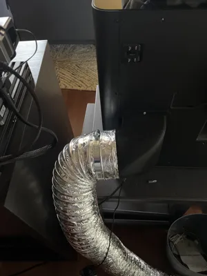
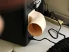
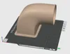
This attaches to the rear of the printer using the 3 “mystery holes” around the exhaust vent. I used some small sheet metal screws I had laying around.


I designed this because I was unable to find one that met my needs. I needed a 90° bend to the right side of the printer (as viewed from the front) and a 4" hose connection. I found some with reduction to smaller hose connections, but I think that's a bad idea. The fan in the printer in not particularly strong. Reducing the vent size would add some backpressure and reduce the air flow more than is desirable. This one allows the use of a full 4" dryer vent hose.


At the other end of the hose, I just built a plywood panel with a standard dryer vent port in it. When I print ABS or ASA, I can just open my window, insert the panel, and slide the end of the hose onto the dryer vent port. But it makes it easy to remove and keep the window closed at other times. Of course, a permanent installation is another option.


*** Edit ***

By request, I added a sedond print profile for a vent that exits to the left (as viewed from the front). To allow access to all 3 screws, I had to make it stick out a bit farther from the rear, and offset the exit pipe a bit upward. You may still need a 90° screwdriver to tighten the screw behind the exit pipe.


Comment & Rating (44)

Please fill in your opinion
(0/5000)

@DarkArtsLab I tried printing from the provided STEP file, and it looks like there's a void in the ring around the 4" tube section that's causing a weak spot and allows the ring to detach when trying to remove the supports. Loading up the file in Fusion, you can see the void in the YZ cross section, about -117mm from the origin.
(Edited)
The designer has replied
0
Reply
The void is present in the print profile, too, not just the STEP file. It's causing the slicer to add top layers, then tries to print on top of that a few hundredths of a mm above it. This weakness is what's making the bottom section of the ring detach along with the supports when the model is done printing. Below you can see the beginnings of the "top" layers forming along the void, starting on layer 204.
(Edited)
0
Reply
Replying to @gillithonnen :
Interesting. I looked at the print profiles and I can see it. Although it didn't seem to affect the print for me - the supports came away fine. But when I look at my original model in OnShape, it looks perfect - no voids. I have no idea why there should be a void in the 3MF file.
0
Reply
Replying to @DarkArtsLab :
The void is very thin, so I'm wondering if you somehow found a rounding error/bug in OnShape? :) I had switched the supports to tree and build-plate only, and I think the tree supports adhered more strongly than if I had just used the normal supports.
0
Reply
Print Profile
Right side exit - 0.2mm layer, 3 walls, 15% infill
I printed with PLS for ventilation for ASA. Printed perfect with no glassing issues while printing ASA. Had to drill out sheet metal on back of printing very slightly to use screws I had laying around. Beware, the bottom hole around the exhaust fan is very shallow before interference with parts in the printer. Overall very happy with the exhaust port.
1
Reply
cause of my space i had to go straight up, but i do appreciate the raw files saves me work
3
Reply
@rowanwillz would you minding sharing the version your remixed that goes straight up?
3
Reply
Replying to @rtye23 :
Same, I was about to create a version to go up and taper down to a smaller connection
0
Reply
does this fit with the (4 PTFE slot) hub ?
The designer has replied
1
Reply
I just watched the BambuLab video on installing the hub. It appears that it will interfere with the upper right corner of my exhaust vent's mounting flange. But you should be able to use a Dremel tool to cut away that part of the flange to allow the hub to be mounted corrctly. It doesn't look like the vent will interfere with any of the cables or PTFE tube locations on the hub.
1
Reply
Replying to @DarkArtsLab :
thanks! exactly what I was thinking. I’ll give it a try asap, keep you updated
0
Reply
@RVALabs I actually had the same concern, and ended up remixing this model just now to give clearance for the AMS hub. https://makerworld.com/en/models/460730#profileId-369287
0
Reply
Print Profile
Right side exit - 0.2mm layer, 3 walls, 15% infill
Ideal for what i was looking for. Although i need mine to go to the left instead of right so the holes dont line up. Different directionals would be fantastic. Supports were a little difficult to get off. A little adjustment there and layer height may help.
The designer has replied
1
Reply
I added a second print profile for one that exits to the left. When exiting to any other direction except right, the exit port is partially blocking access to one of the screws. I made it stick out a bit farther to the rear, and offset it a little upward to hopefully provide better access to the screws. You may still need a 90° screwdriver to get at the one under the exit pipe. Let me know if it works out for you.
0
Reply
Print Profile
Left side exit 0.2mm layer, 3 walls, 15% infill
Overall good, but because there's no screw hole on the left side (Bambu's fault!) the exhaust never quite sealed for me.
1
Reply
Thanks for sharing this. I needed a vertical version and for a smaller extraction hookup but having the STEP file greatly helped. I was able to quickly establish the base and the mounting hole locations and then design the version I needed.
1
Reply
Print Profile
Right side exit - 0.2mm layer, 3 walls, 15% infill
Printed just fine. It fits and works well.
1
Reply
Print Profile
Right side exit - 0.2mm layer, 3 walls, 15% infill
support was a bit hard to remove. but hey, who cares what it looks like. It's functional and my wife no longer complains about the fume.
1
Reply
Print Profile
Right side exit - 0.2mm layer, 3 walls, 15% infill
Perfect!
1
Reply