This page is mostly for the overview. For detailed instructions see the build manual at: http://reprap.org/wiki/ToyREP_Build_Manual
#Description
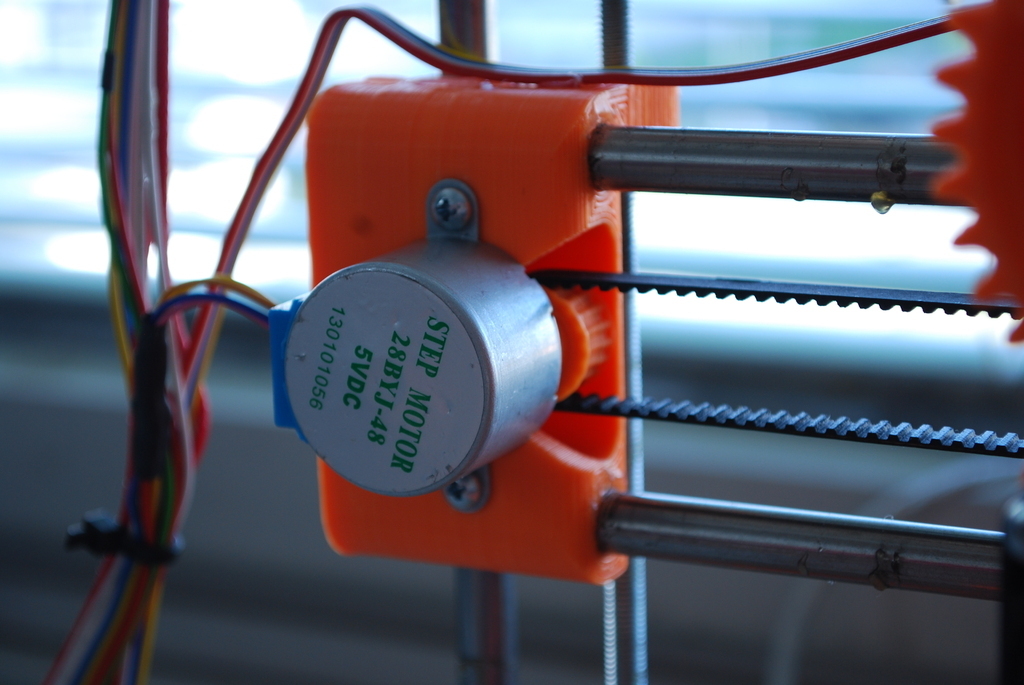
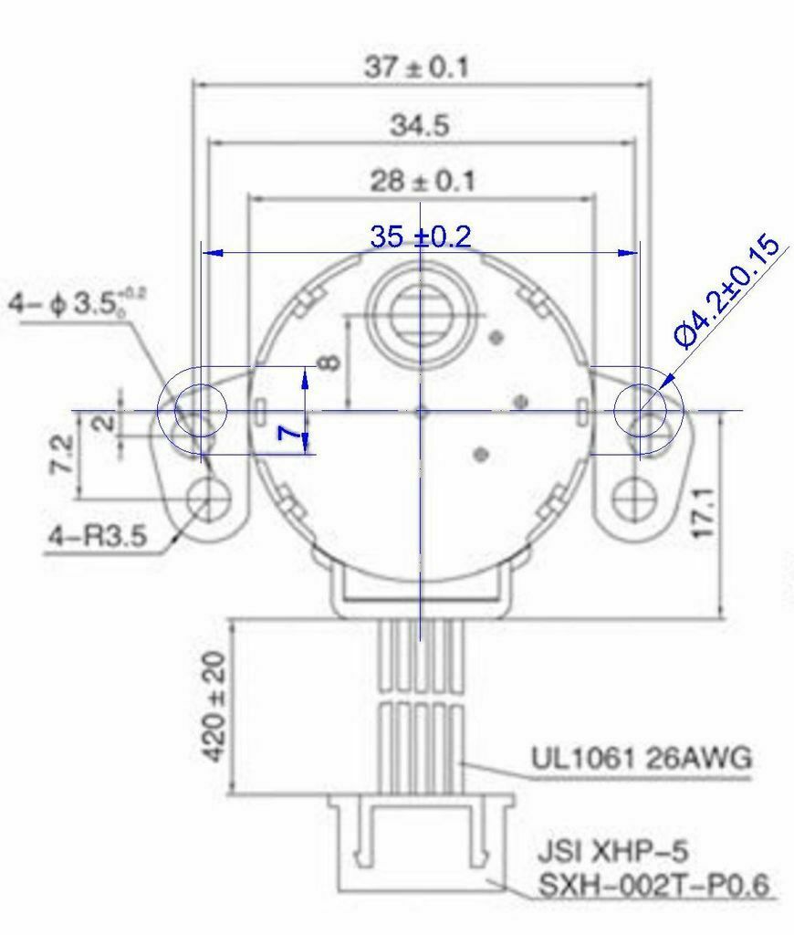
##Motors
Made for 28BYJ-48 stepper motors with bi-polar hack: http://www.electronicsmayhem.com/?p=13
Further reading about this small motor with geared extruder is here: http://grahamwideman.wikispaces.com/Motors-+28BYJ-48+Stepper+motor+notes
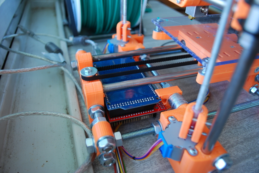
##Electronics
Arduino Mega 2560 with adjusted RAMPS 1.4 can be embedded into the printer, as well as small 12V 40W+ PSU for LED lights (for 78x111x36mm and 129x99x38mm big PSU now) motors are driven with common stepper driver A4988 or DRV8825 with current set to minimum! You can use 1/8, 1/16 or even 1/32 microstepping - not for precision but better current control. Power plugs have to be changed to screw terminals on RAMPS as plugs cannot be installed in tiny space between Z1 and Z2.
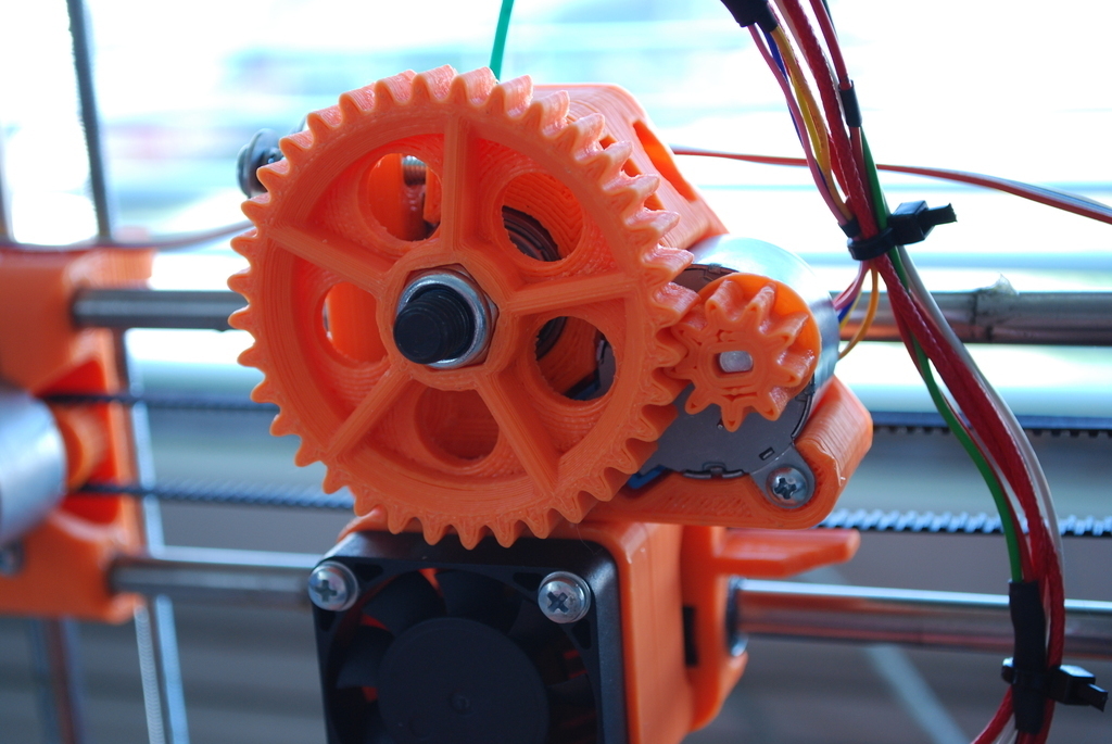
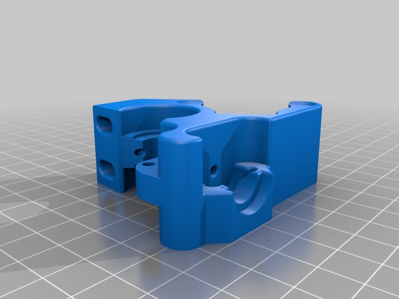
##Extruder
Extruder is geared for better precision and to reduce speed as direct drive would be too quick for the movement speeds this machine can perform. Also to avoid side stress on motors shaft. M8 hobbed bolt is used to drive the filament. Pushed through 608ZZ bearing and in idler also another 608ZZ is used. The motor have power to drive 1.75mm filaments only (but there is also an alternative version for 3mm filament available in improvements).
Although this extruder was designed for Hyena hobbed bolt, it can be used also with common hobbed bolt with hexagonal head with spacing 23, 26 and 30 mm between groove and hexagonal head. Basic gear is designed for 23mm, others are distinguished by spacing dimension in the model name.
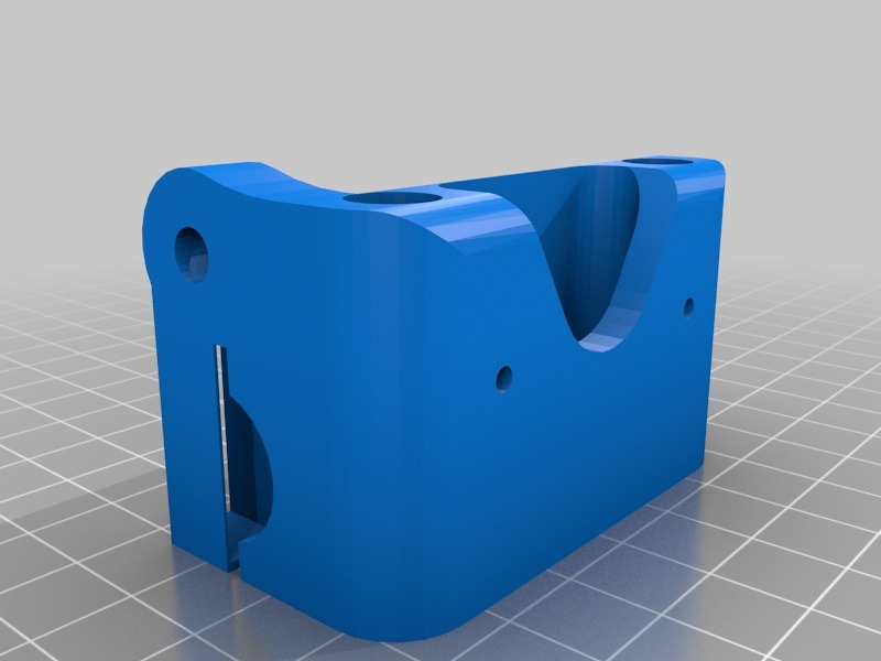
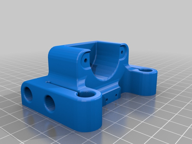
##Hotend
Chines E3D v5 clone is used as a hot end (it have a little bit longer cold end compared to up-to-date v6 original). It is secured to the carriage by fan mount. 12V 40W Ceramics cartridge is used as a heat source with some 100k Ohm thermistor. Cooling fan 40x40x10mm have to be used. It is powered directly by 5V from Arduino or 12V from PSU.
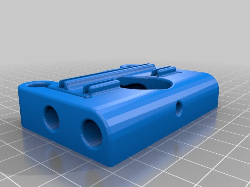
##Movable parts
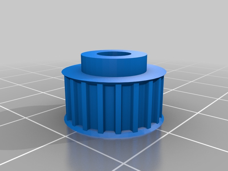
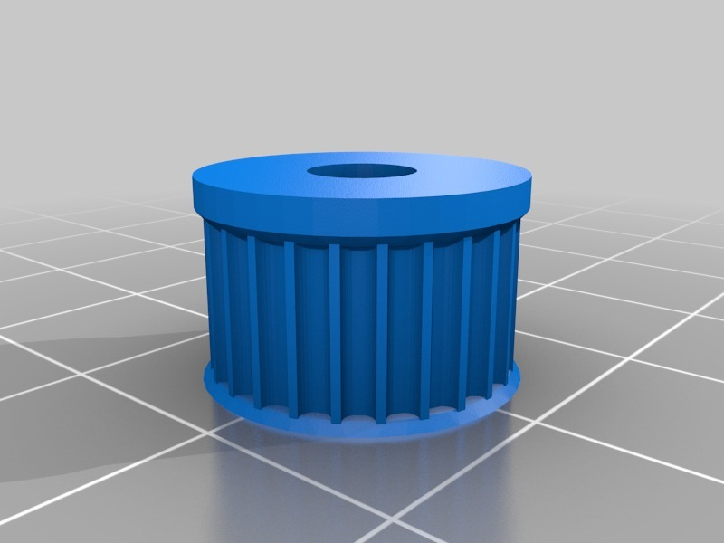
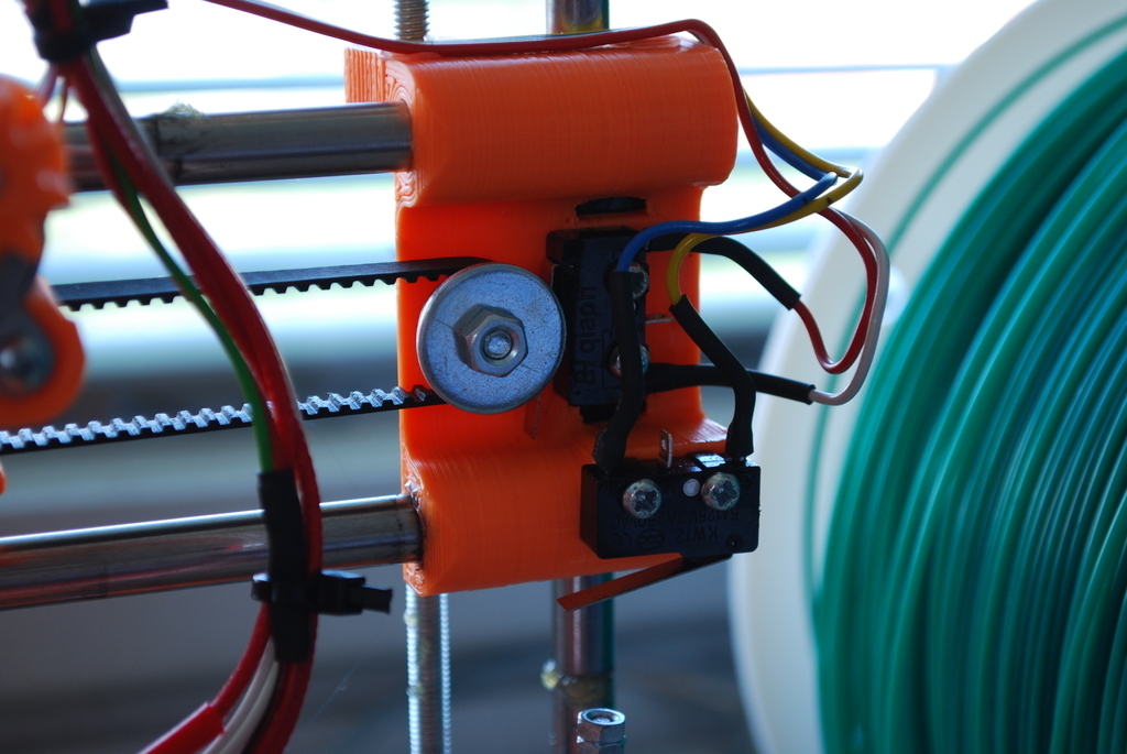
For linear movement LM8UU bearing on 8mm precision rods are used although printed replacement for LM8UU can be used to reduce the price further. My favourite design is this: http://www.thingiverse.com/thing:97041 although I do not have any long term test of them. Models are prepared for T2.5 timing belts as GT2 are harder to print. Pulley have 20 teeth (50mm per turn). The opposite side of the belt is turned around 624ZZ bearing with bigger M6 washer preventing belt to slide off the bearing.
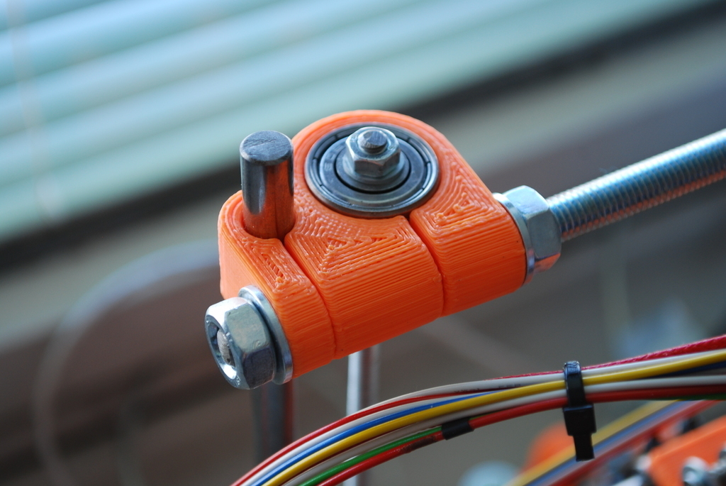
Z axis is pushed by M5 threaded rod. To release stress from motors, threaded rod is suspended from the top, pushed through 608ZZ while centred by 8mm long piece of PVC tube 5/8mm dia tightened from both sides by nuts and washers. Threaded rod is joined with 28BYJ-48 motor by the same PVC tube and tightened by printed Z-joint. M8 threaded rod can be used to speed up Z movement but this design is experimental.
Lengths of smooth rods are listed bellow and in BoQ along witch threaded rods for printer frame.
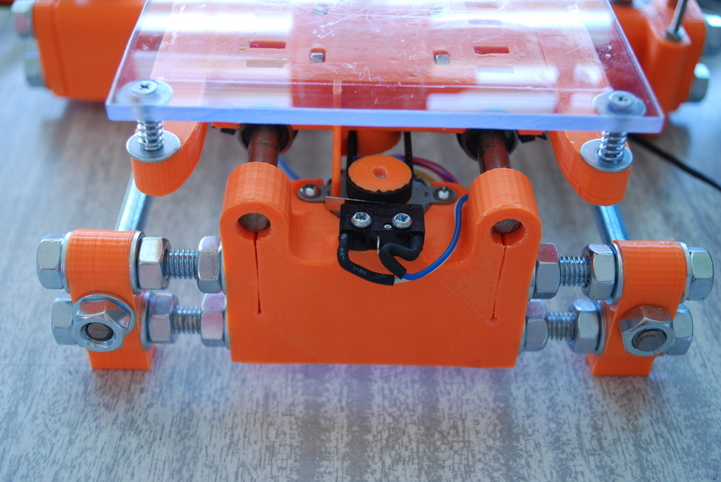
##Endstops
Endstops are mechanical with flat lever and 2.5mm dia. mounting holes 9.5mm apart. In X and Y axis push pin is already printed on carriage and frog. In Z axis ca 85mm long piece of M3 threaded rod have to be used so the distance of the nozzle from bed can be adjusted.
##Print area
Use either 120x120x3mm piece of polycarbonate with mounting holes 105mm apart in each corner as a coldbed or 40W PCB heatbed with 3mm glass sheet designed by Dan Kolar. Mounting of the bed is the same in both cases. For glass you will need additional clamps.
##Frame
Construction is mostly done of M8 threaded rods. Their lengths are as follows:
###Legs
- threaded rod M8x170mm - 4 pcs - in the front and rear frame
###X axis
- threaded rod M8x255mm - 3 pcs - those are parallel with X axis
- smooth rod 8x245mm - 2 pcs - for X axis
###Y axis
* threaded rod M8x245mm - 2 pcs - those are parallel with Y axis
* smooth rod 8x225mm - 2 pcs - for Y axis
###Z axis
* smooth rod 8x290mm - 2 pcs - for Z axis
* threaded rod M5x250mm - 2 pcs - for Z axis movement
* threaded rod M3x90mm - 1 pc - for Z endstop
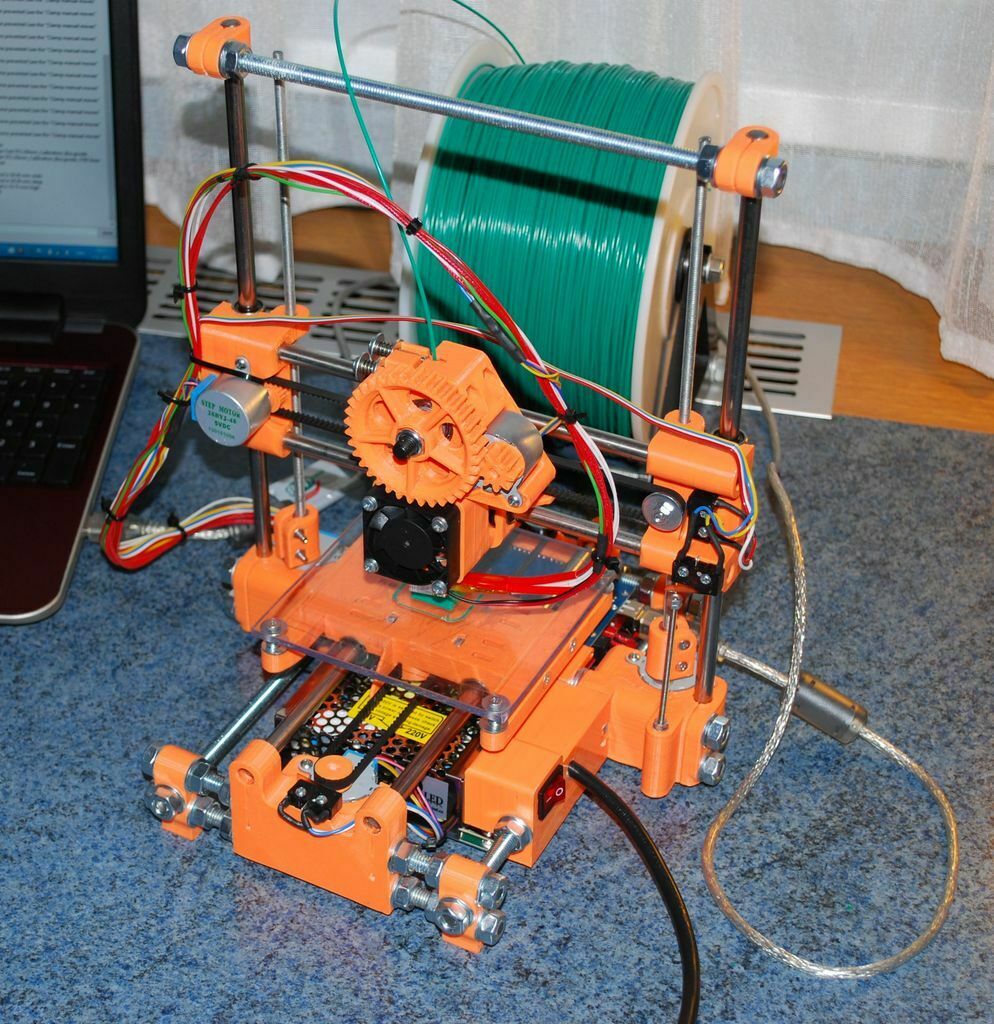
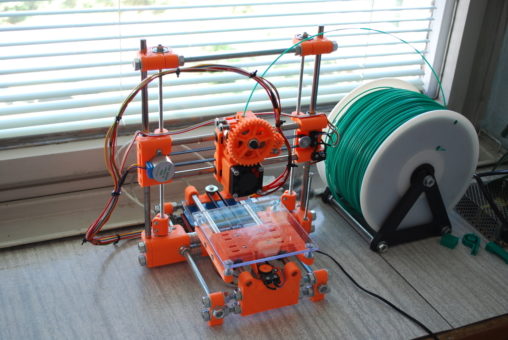
This is default/recommended setup for printer with embedded PSU 111x78x36mm and Arduino but without filament spool placed on top of the printer.
If anybody would like to place spool on top of the printer than I would recommend to prolong Z axis smooth rods by a radius of your spool + 20mm and make one additional threaded rod for X axis, which will hold the spool.
I've got another slightly bigger PSU at home of size129x99x38. Seems to me, this kind is more common but will also make the printer much bigger. For this one, rods would have to be 10mm longer in X axis and legs, also 20mm longer in Y axis. Print area may then grow up to 125x125 instead of 100x100mm.
The last option is to make entirely plain printer without PSU and Arduino embedded and with print area 100x100mm. For that you may use 15mm shorter rods in X and Y axis direction. It would give you the smallest ToyREP possible.
Otherwise M3, M4 screws and nuts are used. Motors are attached by 3x13 wood screws and endstops are attached by 2,5x10 wood screws.
##Assembly
The only crucial measurement during the construction of ToyREP is distance between Z1, 2 and between legs in X and Y axis direction. The rest is usually placed centred, on the edge of the rod or in such way, that something like Arduino have to fit in between two parts.
For machine with 111x78x36 PSU and/or 100x100mm print area is the distance between Z1 and Z2 120mm. The distance between Z1,2 and front legs is 103mm.
For machine with 129x99x38 PSU and/or 125x125 mm print area is the distance between Z1 and Z2 130mm. The distance between Z1,2 and front legs is 128mm.
Machine without PSU and Arduino and with only 100x100mm print area have the distance 105mm between Z1 and Z2. The distance between Z1,2 and front legs is 103mm.
#Putting
into operation
Wire Ramps as per the schematic you will find on internet. If You are not using heatbed, than 11A power supply is not used as well as heatbed D08 and heatbed thermistor T1. Keep in mind that ends stops are (from left to right) X_min, X_max, Y_min, Y_max, Z_min, Z_max and last one is I2C bus. You will use X_max, Y_max and Z_min. Before you will try to move the printer, set at least the micro stepping to 1/16 and current from 90 to max. 150mA on the stepper drivers!
Following part is a bit of calibration and testing. Read it first, than set basic values to firmware and load it to Arduino. Than return to the points where it is required, measure, recalculate and load again and again until all the steps are completed. For Marlin 1.0.2 firmware change the lines as follows (For other firmwares this may be a bit different).
##Electronics
For Arduino Mega 2560 with Ramps 1.4 - one extruder and no heatbed, I am using MOTHERBOARD 33 as the PWM fan may be useful. But you can use different electronics so set it accordingly.
  #define
 MOTHERBOARD 33 // (Power outputs: Extruder, Fan, Bed)
  #define
 EXTRUDERS 1
With Marlin 1.1.0+ consult boards.h file to pick the right type of electronics. Instead of MOTHERBOARD 33 it will look like this:
  #ifndef
 MOTHERBOARD
      #define
 MOTHERBOARD BOARD_RAMPS_13_EFB
  #endif
##Heating
Unless you want to use redundant heat sensor there will be only one thermistor on position T0 for extruder.
  #define
 TEMP_SENSOR_0 1
  #define
 TEMP_SENSOR_1 0
  #define
 TEMP_SENSOR_2 0
  #define
 TEMP_SENSOR_BED 0
Eventually if using also heatbed change the last line to:
  #define
 TEMP_SENSOR_BED 1
Some versions of Marlin can show actual power consumption of hotend. Measure the voltage of your PSU under load an put it into equation instead of both 12.0V. 40W Heat cartridge have resistance 3.6 Ohm. Again, you can measure ours precisely with multimeter. Don't forget that multimeter have internal resistance that you have to measure separately an deduce from measured value.
  #define
 EXTRUDER_WATTS (12.0*12.0/3.6) //  P=I^2/R
For heatbed uncomment also next line. The resistivity may vary from 3.6-4.8 OHM
  #define
 BED_WATTS (12.0*12.0/4.8)      // P=I^2/R
If your firmware supports PID for thermal control, than for Chinese extruders with ceramics heat cartridges you can use following numbers. Latter you can use code M303 S200 in Pronterface to find your numbers and place them there instead.
  #define
 PIDTEMP
  #define
 BANG_MAX 255
  #define
 PID_MAX 255

  #ifdef
 PIDTEMP
    #define
 PID_FUNCTIONAL_RANGE 100
    #define
  DEFAULT_Kp 16.51
    #define
  DEFAULT_Ki 0.87
    #define
  DEFAULT_Kd 78.47
  #endif
 // PIDTEMP
With heatbed you can also uncomment PIDTEMPBED. For ToyREP's 30W 100x100 PCB heatbed use following numbers. Eventually you can find your own PID with code M303 E-1 C8 S90 in Pronterface
  #ifdef
 PIDTEMPBED
    #define
  DEFAULT_bedKp 377.26
    #define
  DEFAULT_bedKi 74.27
    #define
  DEFAULT_bedKd 479.07
  #endif
##Endstops
When setting up the printer keep in mind that you have endstops in X max, Y max and Z min.
  #ifdef
 ENDSTOPPULLUPS
   #define
 ENDSTOPPULLUP_XMAX
   #define
 ENDSTOPPULLUP_YMAX
//    #define
 ENDSTOPPULLUP_ZMAX
//    #define
 ENDSTOPPULLUP_XMIN
//    #define
 ENDSTOPPULLUP_YMIN
    #define
 ENDSTOPPULLUP_ZMIN
  #endif
##Motors
You should disable steppers when the axis is not moving to prevent overheating.
  #define
 DISABLE_X true
  #define
 DISABLE_Y true
  #define
 DISABLE_Z true
  #define
 DISABLE_E true
Stepper in Y axis have inverted direction compared to X, Z and E motors.
  #define
 INVERT_X_DIR true
  #define
 INVERT_Y_DIR false
  #define
 INVERT_Z_DIR true
  #define
 INVERT_E0_DIR true
Also the homing direction is positive in X and Y axis and negative in Z.
  #define
 X_HOME_DIR 1
  #define
 Y_HOME_DIR 1
  #define
 Z_HOME_DIR -1
##Print area
The build volume is 100x100x100mm. To begin with, set the printer as follows, but keep in mind this will not align hot end and print area yet:
  #define
 X_MAX_POS 100
  #define
 X_MIN_POS 0
  #define
 Y_MAX_POS 100
  #define
 Y_MIN_POS 0
  #define
 Z_MAX_POS 100
  #define
 Z_MIN_POS 0

  #define
 MANUAL_X_HOME_POS 100
  #define
 MANUAL_Y_HOME_POS 100
  #define
 MANUAL_Z_HOME_POS 0
After the movement is calibrated you will have to return back to this and measure real coordinates of hot end and print area. You will probably have X, Y homing position somewhere around coordinates 108,101mm:
  #define
 X_MAX_POS 108
  #define
 X_MIN_POS 8
  #define
 Y_MAX_POS 101
  #define
 Y_MIN_POS 1
  #define
 Z_MAX_POS 100
  #define
 Z_MIN_POS 0
Homing position is outside the printing area so:
  #define
 MANUAL_X_HOME_POS 108
  #define
 MANUAL_Y_HOME_POS 101
  #define
 MANUAL_Z_HOME_POS 0
##Speeds and units
Now speeds, steps per unit and acceleration needs a bit of math and testing.
Motors have 32 steps per turn, the gear is not exactly 1:64, but for the first run and tests it will be OK. I recommend using 1/16 micro stepping. 20 teeth T2.5 pulleys have ca 50mm circumference. M5 have pitch 0.8mm (M8 have 1.25mm). The gear on extruder is 1:4 and hobbed bolt have usually 6.0mm dia. Each 28BYJ-48 motor should be able to do 15RPM for sure. So:
In X and Y it should be capable of = 15x50 = 750 mm/min
In Z = 15x0.8 = 12 mm/min
  #define
 HOMING_FEEDRATE   {750, 750, 12, 0}
Use these numbers in Pronterface until you will find quicker ones when steps per unit is calibrated precisely.
In X and Y set default steps per unit = (32x64x16)/50 = 655.36 microsteps/mm
In Z = (32x64x16)/0,8 = 40960 microsteps/mm
In E = (32x64x16x4)/(6x3,1415) =6953.59 microsteps/mm
  #define
 DEFAULT_AXIS_STEPS_PER_UNIT   {655.36, 655.36, 40960, 6953,59}
Later on, you will move the motor in each axis, measure the distance with calliper and adjust the numbers. For eg. if you move the X carriage 100mm in Pronterface, but you measure 99.7mm, or mark 100mm on filament, extrude 100mm and end up with 1mm leftover then:
X = 655.36/99.7x100 = 657.33
E = 6953.59/(100-1)x100 = 7024.20
Do it for X and Y axis separately. You will probably end up with two slightly different numbers. Although pitch on threaded rods is quite precise, there will be the difference due to motor gearbox, so you have to measure Z axis too. You will end up with something like:
  #define
 DEFAULT_AXIS_STEPS_PER_UNIT   {657.33, 657.10, 40757.73, 7024.20}
Initially set the maximal movement speed to numbers bellow. It is way to much, but will give you a headroom for some experiments. The values represent movement speeds in mm/s.
  #define
 DEFAULT_MAX_FEEDRATE   {50, 50, 1, 5}
When default axis steps per unit is calibrated you can test the maximal speeds In Pronterface. Slightly rise the mm/min value and move the motor for 100mm in X, Y or 10mm in Z. Repeat this up to the point when the motor do not have enough torque to move. Then return 10% back from the last working value to be sure and use it from now on. There is only one value for X and Y axis, so pick the lower one.
You will end up with something like 2200mm/min in X, 2000mm/min in Y, 21mm/min in Z and 250mm/min on extruder. Divide these numbers with 60 seconds and put them to firmware to prevent future failure.
  #define
 DEFAULT_MAX_FEEDRATE   {30, 30, 0.35, 4.17}
##Acceleration
Acceleration is way different from common NEMA17 motors. I did not find any easy way how to measure or calculate the values. I only have a simple equation. If you are going to move in axis X 100mm, with top speed 30mm/s, it should finish in 100/30= 3.33 seconds. If the maximal acceleration of the printer would be (100x30)/(100/30) = 900, the printer would not almost use it and that is wrong. This machine can do safely 750mm/min in X axis = 12.5mm/s so 100x12.5/(100/12.5) = 156.25. That may be to low, so you will have to elaborate a bit and find your numbers within these limits. For Z and E the numbers are coming out really low with this method, so you will and up doing it try-and-error anyway.
  #define
 DEFAULT_MAX_ACCELERATION   {300, 300, 1, 17}

  #define
 DEFAULT_ACCELERATION   150
  #define
 DEFAULT_RETRACT_ACCELERATION   17
It is good idea to force the acceleration whenever the printer is moving, but it gets too slow. The values bellow should be enough.
  #define
 DEFAULT_XYJERK   5.0
  #define
 DEFAULT_ZJERK   0.01
  #define
 DEFAULT_EJERK   0
:format(webp)/https://fbi.cults3d.com/uploaders/20227092/illustration-file/178ecec3-571c-495f-bed7-549bf708454b/2015-08-02_ToyREP-Final.jpg)


/https://preview3d-images.cults3d.com/d0h4sliyouwsrqdjq5zlx3jjfplp)
/https://preview3d-images.cults3d.com/6pkswdi15ks83u3q804pve4ixuba)
/https://preview3d-images.cults3d.com/66r8x0pr3xvnpkngk2nezef28pex)
/https://preview3d-images.cults3d.com/hfi7qbsgkg9turluums70g1vb7it)
/https://preview3d-images.cults3d.com/fsuu5carore645nlxn9b0qplc97o)
/https://preview3d-images.cults3d.com/2rkna21lfzrhzcq1m1907jrcadx5)
/https://preview3d-images.cults3d.com/pql3uxhty64li1uolo922gx0qm04)
/https://preview3d-images.cults3d.com/h2vbzx1dsy61xgde1pezi5hu7rfw)
/https://preview3d-images.cults3d.com/qrrlmz484kk0dubxb1x3yyxrwkep)
/https://preview3d-images.cults3d.com/avv7l8mc89g5q11kq17whqca0m34)
/https://preview3d-images.cults3d.com/sallyzn4ghwslyk5wb4aciact5z1)
/https://preview3d-images.cults3d.com/dd9goqmk9nyi5cnkm5r0xh7w4y5a)
/https://preview3d-images.cults3d.com/nkd9nw0mmasokgdb8p3ua4uhpvsi)
/https://preview3d-images.cults3d.com/6p0efpo5869ts1sz7ivnrezjodjq)
/https://preview3d-images.cults3d.com/623pe0cpl0r4frlo9kyup0oapimv)
/https://preview3d-images.cults3d.com/c3iityaco69e3raw4qrpuy52bsug)
/https://preview3d-images.cults3d.com/919dy2hcu1i9r49j1xbk8gtqz5cr)
/https://preview3d-images.cults3d.com/mybmtz1tarik3c2ios2aj50ngnn8)
/https://preview3d-images.cults3d.com/3v5uzvw667ifeupl2tj5ud9sa37f)
/https://preview3d-images.cults3d.com/mqrs6q6wanuomh2gspwd2m7ytifp)
/https://preview3d-images.cults3d.com/54dwtfpo4ajh8aakcfmxp229rlz6)
/https://preview3d-images.cults3d.com/lqimd8u9ec1o6el4e6nr1emqfgap)
/https://preview3d-images.cults3d.com/82xo794bz7m962nel09tb1sqvobh)
/https://preview3d-images.cults3d.com/5ta4kyr0dq67yz5lpa19g9g42x3b)
/https://preview3d-images.cults3d.com/dagx8d778utr2bslsb1g9rc2pozt)
/https://preview3d-images.cults3d.com/ispi8whcy7xzfkgd7332j1c9ws83)
/https://preview3d-images.cults3d.com/8qqyuxxojsoui57mxewl2kudpitw)
/https://preview3d-images.cults3d.com/5os66d69sv9bjp1fesntyb9gj6ym)
/https://preview3d-images.cults3d.com/o61cfnadrae63y36lzzllxkq7ffp)
/https://preview3d-images.cults3d.com/3r6tbx5dsrisboz0kjnal5wrc26d)
/https://preview3d-images.cults3d.com/lmobx1ad6uotgpplmhbp0sqi5ior)
/https://preview3d-images.cults3d.com/czh59k6arh6uocwxrenx3oyb0lbo)


:format(webp)/https://fbi.cults3d.com/uploaders/20227092/illustration-file/948b51fb-2665-47fa-9fb1-1a2ead886a16/7g_cup_full.jpg)
:format(webp)/https://fbi.cults3d.com/uploaders/20227092/illustration-file/cc43cae4-ad6a-494e-8d7a-6995dfd947e2/be6d4911-9396-4787-8965-89c38c21d868.jpg)
:format(webp)/https://fbi.cults3d.com/uploaders/20227092/illustration-file/d681915a-6c8e-4ddf-b8d9-c47224479fd5/2015-03-16_Assembly_2.JPG)
:format(webp)/https://fbi.cults3d.com/uploaders/20227092/illustration-file/1f978155-b4d3-403e-a169-e64ca480cc6f/LED_light_top.jpg)