3D model description
This is the first version of a flying pendulum toy made for fun on a 3D printer we recently got. I made something like this with some scraps of wood, brass tubing and paper clips decades ago and would suggest you do the same if you have even modest skills, but it was fun to design and get this working as a 3D print.
Place a rubber band in the hook on the bottom of the rotor spindle and attach it to the hook on the mast. Tie a thread on the weight, pass it through the loop on the end of the rotor and attach it to the cleat. Cleat the weight high enough so it doesn't drag across your tabletop. It's easiest to wind up by holding upside down and spinning the counterweight side of the rotor with your finger. If properly balanced and with the right rubber band, it will run for about 4-5 minutes.
The files include a fully assembled base and rotor as well as individual parts for screwing together. I also made a wider base, though I found the 50 mm x 200 mm base to be wide enough. You can try scaling the entire model down, but I found this was about the smallest that would run smoothly without excessive binding as a 3D print.
A heavier weight seems to prevent it from swinging too high and throwing half hitches, so I suggest 100% infill for both the weight and counterweight.
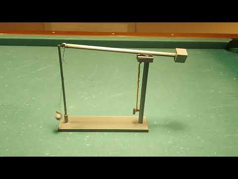
The fully assembled model is 26 cm long by 5 cm wide and 18 cm high (about 10" x 2" x 7"). The rotor arm swings a 16 cm (6") radius circle.
I'll be making some different variants of this and will also improve the threads once I learn how to use Fusion 360 better. Meanwhile let me know if you have specific design requests or need any changes, and of course please contact me if you plan to sell this model. I am new to design and printing so please let me know if you notice anything wrong!
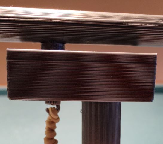
Improved rotor, 2022-01-08 (see pictures of hook and cleat):
1) Changed loop on spindle to a hook for easier attachment of rubber band. This will be weaker than the loop but has held up OK so far.
2) Added a cleat on top of the rotor so it's not necessary to tie a knot in the thread here.
3) Made loop on end of rotor arm smaller to hold weight closer to post.
3D printing settings
I printed this in PLA on a Prusa Mk3S+ at 0.2 mm and had no issues with the screw threads. Total print time was about 8 hours. A higher resolution will of course yield cleaner results but print time will go up. I tried printing the long parts in various orientations (including vertical) with and without supports (except the obvious ones) and at various infill percentages and had no serious problems, but the parts with inside threads are certainly best printed with their axis vertical and without support material. If you print the long parts oriented vertically, the threads may be cleaner, but the parts will not be as strong. If you print the rotor with the spindle facing up, it may spin better, but the spindle could snap off, so I'd suggest printing these parts horizontal with their extensions facing out to the side for best strength. I printed the weight and counterweight with 100% infill. I did the absolute minimum postprocessing, just making sure I had removed almost all support material.
Troubleshooting:
- You may need to smooth or even pare down the spindle on the rotor to prevent it from binding, depending on what orientation you choose to print it in.
- Use very fine sandpaper to smooth the wrapping post if the thread snags on it. 220 grit worked for me.
- If the rotor binds because the rubber band is too tight, use a longer rubber band, or string two or more rubber bands together.
- If the rotor spins too fast and the weight swings up and gets stuck, don't wind it up so far or use a lighter rubber band. You can also try scaling up the weight to make it heavier.
https://www.youtube.com/watch?v=QLtOCefaKJQ
:format(webp)/https://fbi.cults3d.com/uploaders/20559472/illustration-file/105edb9f-4139-48c2-a740-cce7fa926a91/Flying-pendulum.gif)

/https://preview3d-images.cults3d.com/variants/fvk8u4dle0cteqexzh90diw9dxjb/77d3f3b93f425080e8527932a83b54282f99f31ca9700de02f554c0ba0d78731)
/https://preview3d-images.cults3d.com/variants/18u93gbvhzrk3jn5ir4qd9jbmpf5/77d3f3b93f425080e8527932a83b54282f99f31ca9700de02f554c0ba0d78731)
/https://preview3d-images.cults3d.com/variants/ynsl7eesx9v08zbj0ybe5ywv0kvk/77d3f3b93f425080e8527932a83b54282f99f31ca9700de02f554c0ba0d78731)
/https://preview3d-images.cults3d.com/variants/cpq5sanhmsv4okpmkouq36zht3kg/77d3f3b93f425080e8527932a83b54282f99f31ca9700de02f554c0ba0d78731)
/https://preview3d-images.cults3d.com/variants/er69lvutj9bbowd8g4qilzawyfss/77d3f3b93f425080e8527932a83b54282f99f31ca9700de02f554c0ba0d78731)
/https://preview3d-images.cults3d.com/variants/v5hi3iowrl1vncaulnhchpt850nu/77d3f3b93f425080e8527932a83b54282f99f31ca9700de02f554c0ba0d78731)
/https://preview3d-images.cults3d.com/variants/r72t9efewctpqaa07c7emmlma38w/77d3f3b93f425080e8527932a83b54282f99f31ca9700de02f554c0ba0d78731)
/https://preview3d-images.cults3d.com/variants/t0l6s0521ht8o5laa7smoh2j5scr/77d3f3b93f425080e8527932a83b54282f99f31ca9700de02f554c0ba0d78731)
/https://preview3d-images.cults3d.com/variants/23qnzm9lyb6lg7c50wqh3iagsxfh/77d3f3b93f425080e8527932a83b54282f99f31ca9700de02f554c0ba0d78731)
/https://preview3d-images.cults3d.com/variants/gvijkbg24fmgr35cqnjlxvbhf9hs/77d3f3b93f425080e8527932a83b54282f99f31ca9700de02f554c0ba0d78731)
/https://preview3d-images.cults3d.com/variants/i20gmkzzhtjp1012dygkxua89ote/77d3f3b93f425080e8527932a83b54282f99f31ca9700de02f554c0ba0d78731)


:format(webp)/https://fbi.cults3d.com/uploaders/20559472/illustration-file/712d58da-75d3-42a0-94e6-cc4ca29fae1a/320-short.gif)
:format(webp)/https://fbi.cults3d.com/uploaders/20559472/illustration-file/90daba23-84d0-42ab-83fa-fe8be969bbd9/IMG_20240121_160119498.jpg)
:format(webp)/https://fbi.cults3d.com/uploaders/20559472/illustration-file/14f1c1a5-102a-4e92-8247-2c145976f65d/IMG_20231124_112049422.jpg)