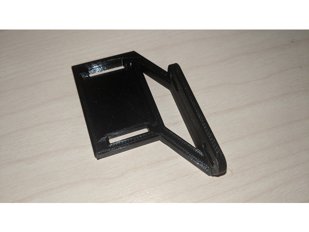
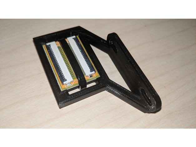
This is a customisable riser for an FFC (flexible flat cable) extension PCB.
This riser is intended for use on a Sidewinder X1 with either:
* the stock extruder assembly
* an aftermarket extruder assembly (such as the E3D Hemera).
Please note that when you use this riser on a Sidewinder X1, you will not longer be able to use the stock breakout board cover.
Purpose
The riser serves two potential functions:
1. Flexible flat cable height adjustment
Firstly, it can be used to raise the height of the FFC connector to prevent the flexible flat cable from rubbing against the X axis pulley wheel. In particular, when fitting aftermarket extruders such as the E3D Hemera, the position of the FFC can be lowered (depending on how it is mounted). This riser can be used to raise the height of the FFC connector via an FFC extension PCB.
Before
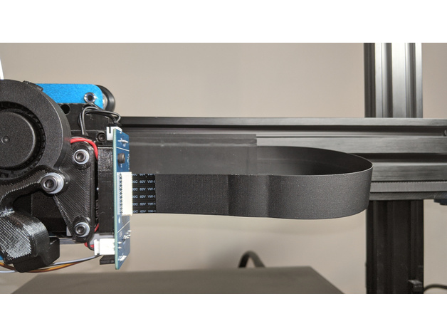
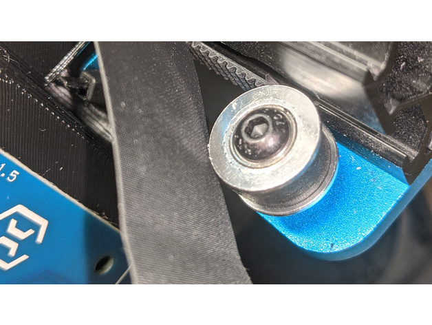
After
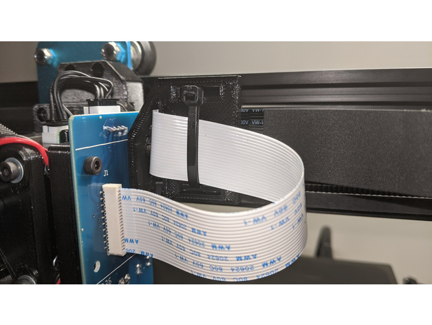
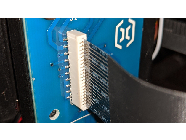
2. Securing flexible flat cable connection
Secondly, it can help prevent the flexible flat cable from becoming loose. The FFC connectors on the breakout board of later versions of the Sidewinder X1 (such as the V4) do not have clips. As a result the flexible flat cable can work itself loose over time. A number of supports exist to help prevent this, however some FFC extension PCBs have connectors with clips. Using such FFC extension PCB with clips will help to secure the flexible flat cable.
Before
After
Work in progress and future versions
This Thing is marked as a work in progress. Sharing your makes and comments will help me improve this design.
Customisation
This riser is highly customisable. You can customise everything from the material thickness and offset of the PCB mount to the size of the PCB recess and the screw holes.
STLs
A few pre-configured STLs are included that have been rotated for printing (Rotate_For_Printing option enabled):
codeandmake.com_Sidewinder_X1_FFC_Riser_v1.0_E3D_Hemera_(parallel).stl - This is an export of the default settings. This should be ideal for an E3D Hemera extruder assembly (using the recommended or similar printed mount). This has not been tested - please share your makes and comments.
codeandmake.com_Sidewinder_X1_FFC_Riser_v1.0_E3D_Hemera_(perpendicular).stl - This is an export with the the Inner_Cable_Slot_Offset value set to '0' and the Parallel_PCB_Mount and Outer_Cable_Slot options disabled. This should be ideal for an E3D Hemera extruder assembly (using the recommended or similar printed mount).
codeandmake.com_Sidewinder_X1_FFC_Riser_v1.0_Stock_(parallel).stl - This is an export with the PCB_Mount_Vertical_Offset value set to '0'. This should be ideal for the stock extruder assembly. This has not been tested - please share your makes and comments.
codeandmake.com_Sidewinder_X1_FFC_Riser_v1.0_Stock_(perpendicular).stl - This is an export with the PCB_Mount_Vertical_Offset and Inner_Cable_Slot_Offset values set to '0' and the Parallel_PCB_Mount and Outer_Cable_Slot options disabled. This should be ideal for the stock extruder assembly. This has not been tested - please share your makes and comments.
You will need
For fitting to a Sidewinder X1 you will need:
- 2x M3 screws (see note below)
- Up to 2x M3 nuts (square or regular) - This depends on how your breakout board is mounted
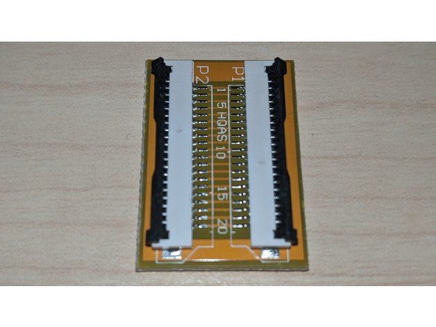
- 1x 20 pin, 1mm pitch FFC extension PCB
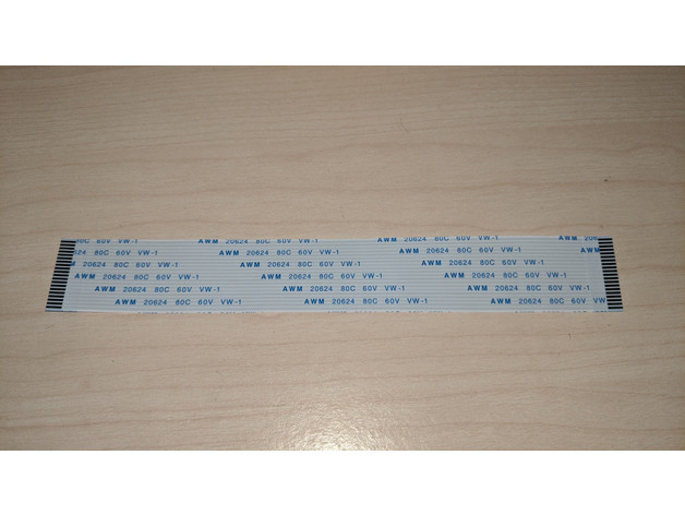
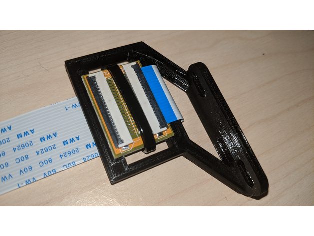
- 1x 20 pin, 1mm pitch FFC cable with same-side connections (ideally about 10cm - the one pictured is 15cm which is sligtly too long)
- A cable tie
- Some double-sided tape or a sticky foam pad (optional)
A note on screws
To attach this riser you will probably need slightly longer M3 screws than the ones currently being used to mount the breakout board (not the stock cover) to the Sidewinder X1.
You will probably need to add the Material_Thickness of this riser to the length of your existing screws. The default material thickness is 3mm.
If you are unable to obtain the exact lengh you can use slightly longer screws with some washers.
I am using this Hemera mount. I originally used 8mm screws to attach the breakout board to the circuit board mount and I am now using 12mm screws to mount this riser.
Installing
Customise the riser or use one of the provided STLs and print it
Attach the FFC extension PCB with double-sided tape or a sticky foam pad
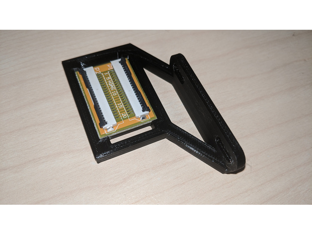
Secure the FFC extension PCB with a cable tie
Connect the new FFC
Attach the riser to your Sidewinder X1 with 2x M3 screws
Connect the new FFC to the breakout board connector
Connect the existing FFC to the FFC extension PCB
Versions
- 1.0 (5 Nov 2020) - Changed variables from camelCase to Underscore_Case and added
PCB_Tie_Slots option.
- 0.3 (1 Feb 2020) - Added
Rotate_For_Printing, Inner_Cable_Slot_Offset and Outer_Cable_Slot_Offset options
- 0.2 (29 Jan 2020) - Added
Parallel_PCB_Mount, Inner_Cable_Slot and Outer_Cable_Slot options
- 0.1 (26 Jan 2020) - Initial version
Printing
Recommended slicer settings:
- Resolution: 0.1mm
- Infill: 50%
- Orientation: The best orientation for printing in will vary depending on the options selected. However, for best results, you should generally print this part with the PCB recess facing up. Enable the
Rotate_For_Printing option to rotate the part in this orientation.
- Supports: Depending on the options selected, it may be necessary to use supports.
- Rafts: Doesn't Matter
License
The "Sidewinder X1 E3D Hemera FFC Riser" models (.stl) are licensed under the CC BY license by Code and Make.
The "Sidewinder X1 E3D Hemera FFC Riser" code (.scad) is licensed under The MIT License by Code and Make.
We are proud to offer content to you absolutely free.
We love to create free content for you. As you might imagine, it takes a lot of time. Supporters help us fund materials and equipment to create future projects and tutorials. To show your appreciation, please use the link below:
https://codeandmake.com/support
We thank you so much for your support!
:format(webp)/https://fbi.cults3d.com/uploaders/16502974/illustration-file/2519a2a3-f6a6-4c7d-bb08-1bea131189b0/riser_fitted.jpg)


/https://preview3d-images.cults3d.com/az1owll2pvkc9tjjnoxjobha8w39)
/https://preview3d-images.cults3d.com/variants/ob3uj3xdg51ixmh3j9y1lm4rpkai/9ce1a1278a90847fe525f7bdea66ae6081035e320afa813bf6efbbbe4c5d9f85)
/https://preview3d-images.cults3d.com/q7fmc3flh0mjyvwkh6kcckucr631)
/https://preview3d-images.cults3d.com/variants/a5wznur4ozrvubza1vjyb0qcll3r/9ce1a1278a90847fe525f7bdea66ae6081035e320afa813bf6efbbbe4c5d9f85)


:format(webp)/https://fbi.cults3d.com/uploaders/16502974/illustration-file/4294db12-b8a8-4122-81b7-7e377dd858ac/codeandmake.com_Mythical_Horn_Generator_v1.0.png)
:format(webp)/https://fbi.cults3d.com/uploaders/16502974/illustration-file/667f3a9d-fea2-4df8-970a-8334dfeebe8f/codeandmake.com_Blade_Glasses_v1.0.gif)
:format(webp)/https://fbi.cults3d.com/uploaders/16502974/illustration-file/ad7c4719-6434-4396-9212-0f2e970c76c8/codeandmake.com_Circular_Coin_Rack_v1.0.jpg)
:format(webp)/https://fbi.cults3d.com/uploaders/16502974/illustration-file/cfbc51d5-79e1-40b5-8315-bac07789719b/codeandmake.com_Christmas_Tree_Star_Topper_v1.0-2.jpg)