Singer Nähmaschine / sewing machine 6xx (670g, 631g, ...) electronic conversion parts


Singer Nähmaschine / sewing machine 6xx (670g, 631g, ...) electronic conversion parts
Published 2020-08-25T16:41:27+00:00
3D-gedruckte Teile zum Umbau einer Singer 6xx aus den 1960ern auf einen BLDC-Motor und eine elektronische Nadelpositionierung (oben/unten, einstellbar durch den Bernina-Fußanlasser LV1 mit integrierter Nadelpositionsumschaltung:
- Adapter zum Einbau einer Niedervolt-Steckverbinderbuchse für das Pedal und einer Lemo-S-Einbaubuchse für das Netzteil anstelle der originalen Singer-Buchse.
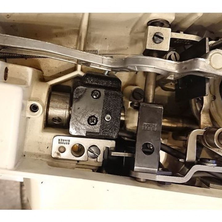
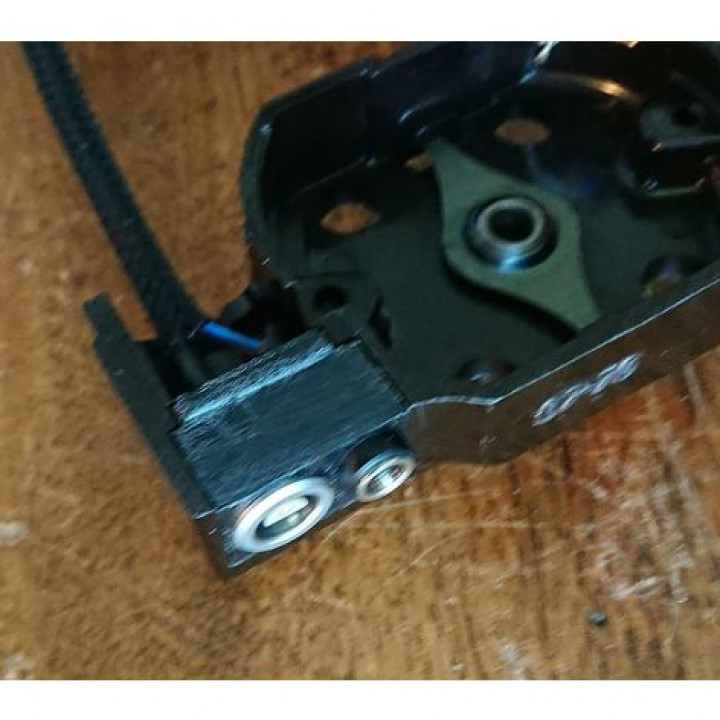
- einstellbarer Halter+Schutzgehäuse für Reedkontakte zur Montage an der Hauptantriebswelle
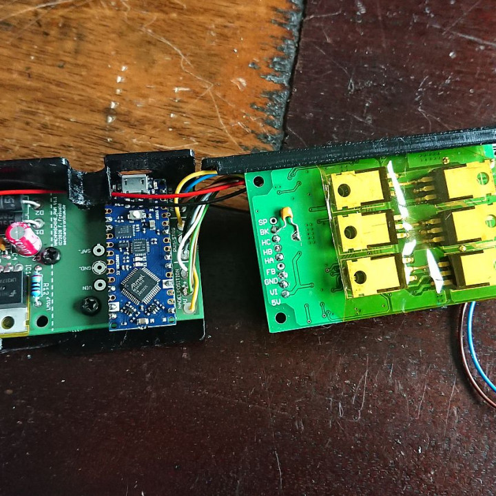
- zwei Gehäusehalbschalen für die Elektronikplatinen zum Einsetzen in das Nähmaschinengehäuse
Hinweis: Die Datei "Reedkontakttraeger_einfach.stl" wird nur benötigt, falls der 3D-Drucker den Reedkontaktträger nicht brauchbar druckt. Dort sind die Schlitze etwas breiter und leicht vereinfacht, man muß aber die Reedkontakte mit Klebstoff fixieren.
Die vollständige Umbauanleitung ist hier zu finden: https://www.mechanotronikum.de/index.php/36771-singer-631g-version-2-0-teil-1.html
Gedruckt aus PETG (PLA sollte aber ebenfalls funktionieren).
Druckeinstellungen:
Layerhöhe: 0,15mm
Infill: 30%
Verwendete Hotenddüsengröße: 0,4mm
--------------------------------------------------------------------
Some 3D printed parts needed to convert a Singer sewing machine from the 1960's to a BLDC motor, with automatic needle up/down ability (controlled by using a Bernina LV1 pedal):
- adapter for a low voltage connector plug for the pedal and a Lemo S series connector to fit into place of original connector. Very tight fit for the connector nuts - you may need to sand the edges or simply glue the connectors in place without using nuts.
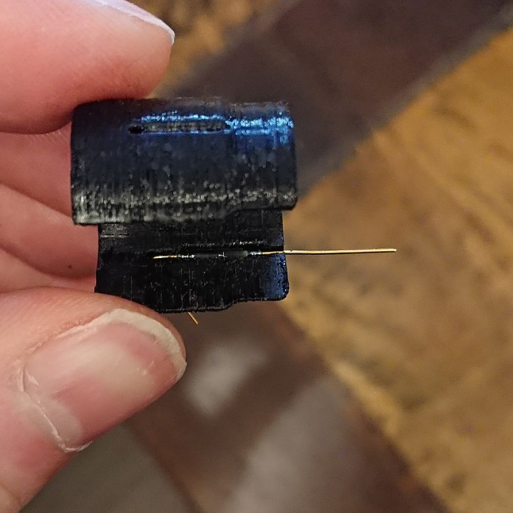
- adjustable holder to fit reed contacts around the main axis of the sewing machine in order to read needle position, constisting of main part "Halter", reed contact holder "Reedkontakttraeger", cover "Abdeckung_Halter" and a position aid "Positionierhilfe".
- cases for the two PCBs to fit them into the machine housing (gehaeuse_lp_arduino.stl and gehaeuse_lp_bldc.stl)
Since the reed contact holder might be rather demanding for some printers, a simplified version ("reedkontakttreger_einfach") is also available, where the wire slots are slightly broader and a bit simpler. You my need to glue the reed contacts there to secure them though.
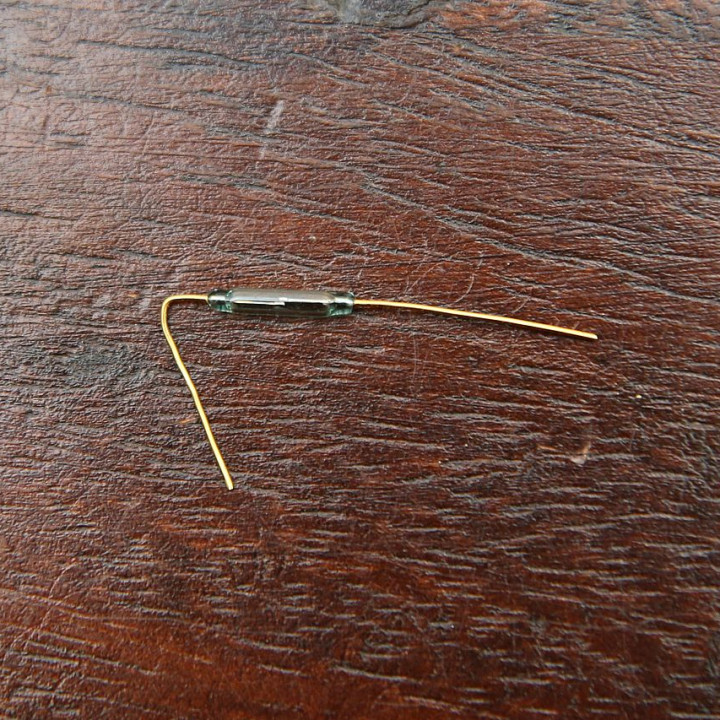
The holder is made for two Ø1.5mm/height 0.5mm neodym magnets and two Ø1.8mm/length 10mm reed contacts (e.g. PIC PMC-1001). Cable for connection can be any 3- or 4-wire cable with 4.5mm nominal outer diameter (I used Lapp Unitronic LIYD11Y 4x0,14).
Detailed instructions with more details on the electronics, the Arduino program and more photos (in german) can be found here: https://www.mechanotronikum.de/index.php/36771-singer-631g-version-2-0-teil-1.html
The cases and the connector adapter ought to be self-explanatory. For the reed contact holder, please observe the following steps after printing:
- Cut M4 threads into the two 3.2mm holes in part "Halter" and insert M4 grub screws.
- Take off upper lid of sewing machine.
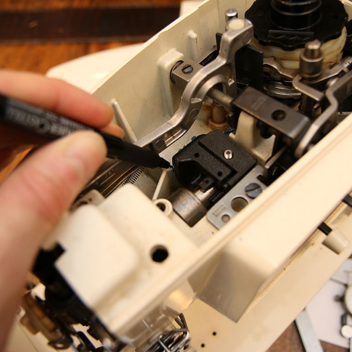
- Insert position aid part into main part, align cutout of position aid with cutout of holder and push the assembly onto the sewing machine main shaft (refer to picture on placement - assembly should have slight press fit if print is correct). Rotate machine handwheel until thread lever arm head has just risen above machine housing. Make a horizontal marking on the handwheel (e.g. with a bit of tape) then turn machine handwheel a further 90°.
- Now mark position of holder on machine case stiffening rib. Mark position of cutouts in position aid on main shaft.
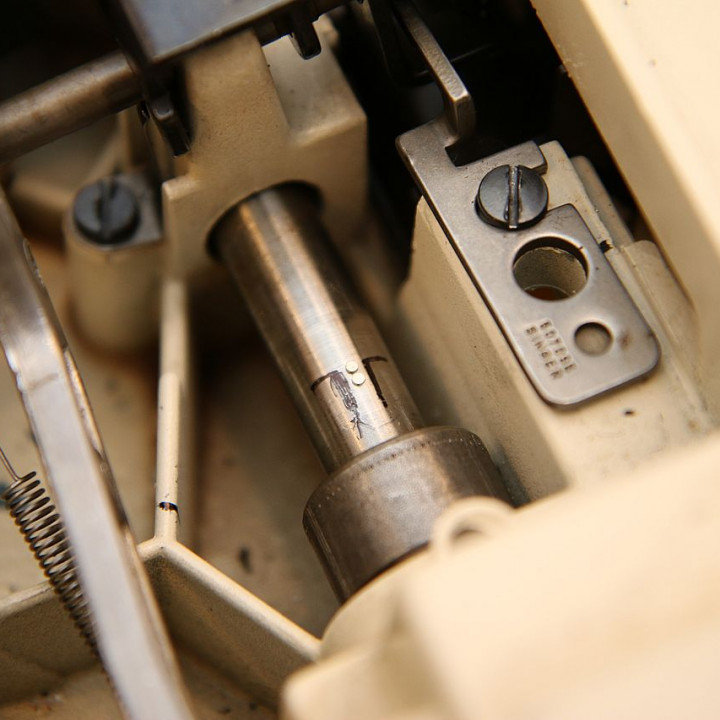
Remove assembly. - Glue two Ø1.5mm/height 0.5mm Neodym magnets axially besides each other onto the machine drive shaft, centered between the marks made with the position aid (same magnetic pole facing outwards - if the magnets try to "flee" from each other, you have them right).
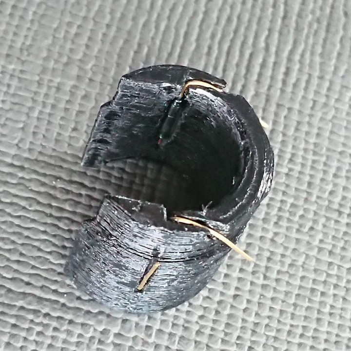
- Bend one wire of the reed contact 90° so that you can insert it into the reed contact holder. It should fit snugly into the excess. Be careful to not apply too much pressure, reed contacts are fragile. Take care to bend the wire exactly into the direction relatively to the inner contacts of the reed contact as shown on the picture!
Bend rear wires around into outer recesses, bend and shorten frontal wires. - Insert cable and reed contact holder into main part. Solder wires to reed contacts, leaving some excess length for altering the adjustment later by rotating the insert.
- Place holder into machine at the place marked before and secure on stiffening rib of housing by tightening the grub screw. If you do not own a miniature ratchet, insert bit into the screw and carefully turn it using pliers.
- turn the handwheel with a multimeter attached to the reed contacts, the contacts should close when the needle is at bottom and at top position. If necessary, fine position reed contacts by rotating reed contact holder - the 2mm rod used before can be inserted into the corresponding hole to get a lever for turning.
- When done, secure reed contact holder in main part by carefully tightening the grub screw on the top and mount the cover with two short (5mm length is good) Ø3mm screws for plastic. The cover secures the cable as well.
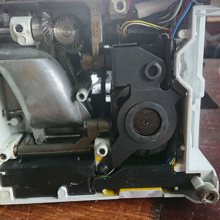
The cases fit into the back lower half of the machine and leave access for the arduino USB port. Remember to isolate the place for the BLDC controller and the transistors (I suggest broad capton tape, please refer to pictures) - it just about fits into the machine housing, so there is no space to properly mount it somewhere. You may need to remove some of the inner ribs of the original plastic machine cover.
Printed with PETG (PLA should work as well), without support structures.


Print settings:
- print height: 0,15mm
- infill: 30%
- used hotend nozzle size: 0,4mm
For the reed sensor parts: THOROUGHLY remove any excess material, especially in the notches for the reed contacts. reed contact holder (file "Reedkontakthalter") and position aid ("Positionierhilfe") should have a slight press fit in the main part "Halter" without visible deformation. Is fit is too tight, sand slightly.
The cases might need some minor sanding at the places where they come into contact with the machine housing. They fit snugly into my two machines - but the cases are 1960s cast aluminium, so I do not know how tight the acceptable tolerances were...
| Date published | 25/08/2020 |
| Support Free | YES |
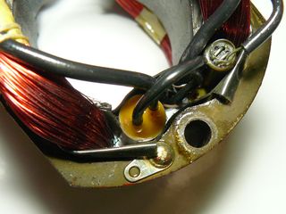
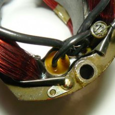
Better replace it, it also saves the motor from voltage spikes :-) Wima MP3-X2 capacitors of the closest value available (e.g. 0,022 instead of the original 0,02 or 0,025 µF are fine.The one in the motor is glued directly next to the coil into the stator (hence the destructive behaviour if it blows up) but will come out if you use a little force. Or you just leave it there and only cut the wires.