Aperçu/Overview
#Français (English below)#
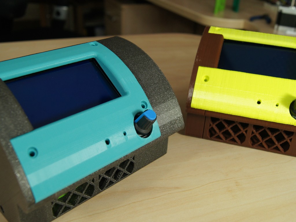
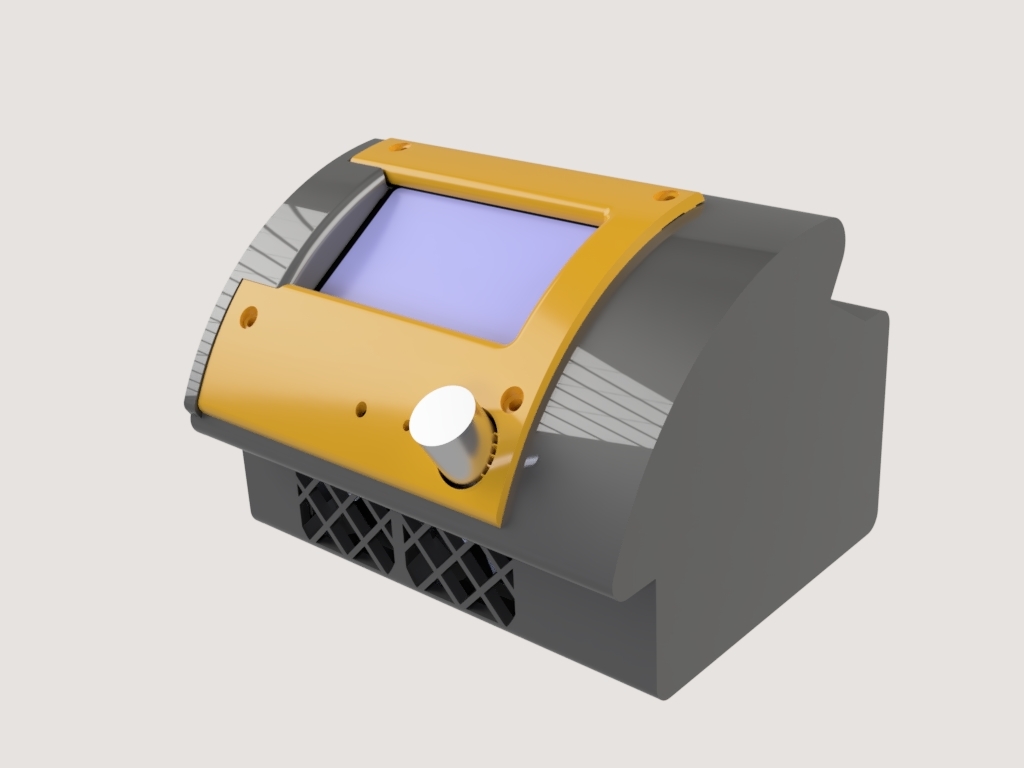
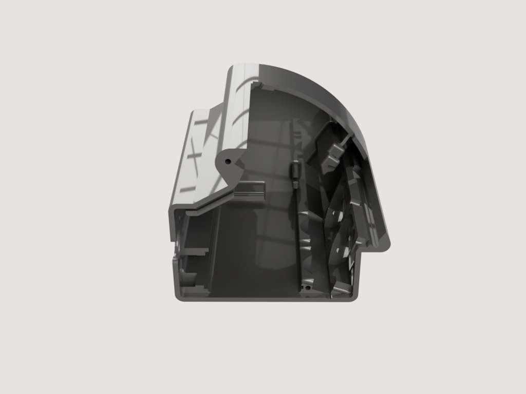
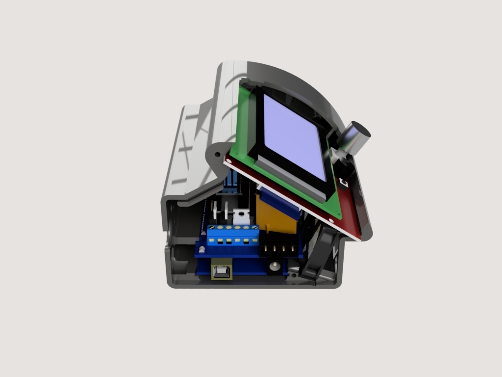
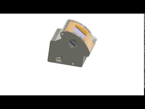
Voici la v4 de mon boîtier pour carte Arduino MEGA + RAMPS + LCD 12864.
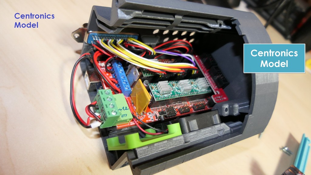
A l'intérieur s'y logent :
- Une carte Arduino Mega
- Une RAMPS (1.4 ou 1.5 ou 1.6)
- Un écran LCD 12864
- Un ou deux ventilateur 40x40x10
Cette pièce est un élément de l'imprimante 3D Delta pliable DeltaFold
##Quoi de neuf dans cette v4 ?##
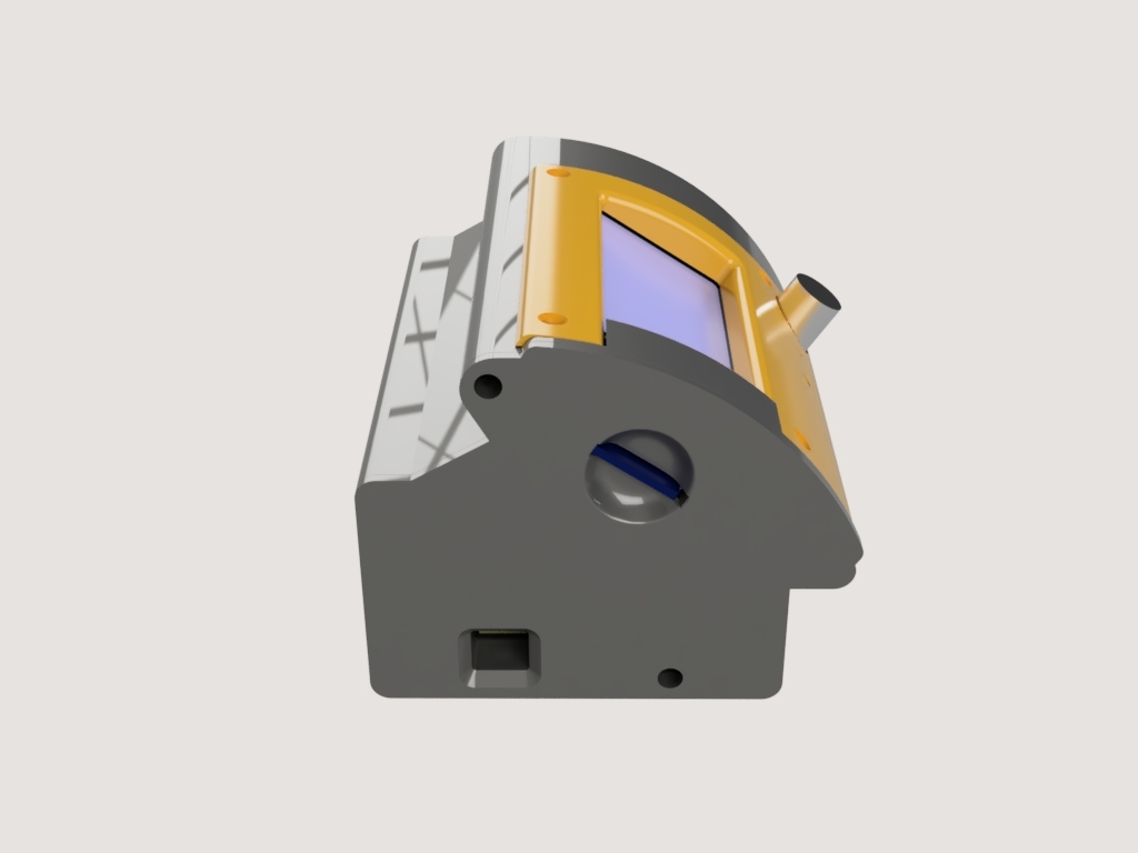
- Deux variantes de raccordement :
- Un simple trou à l'arrière du boitier pour passer tous les cables
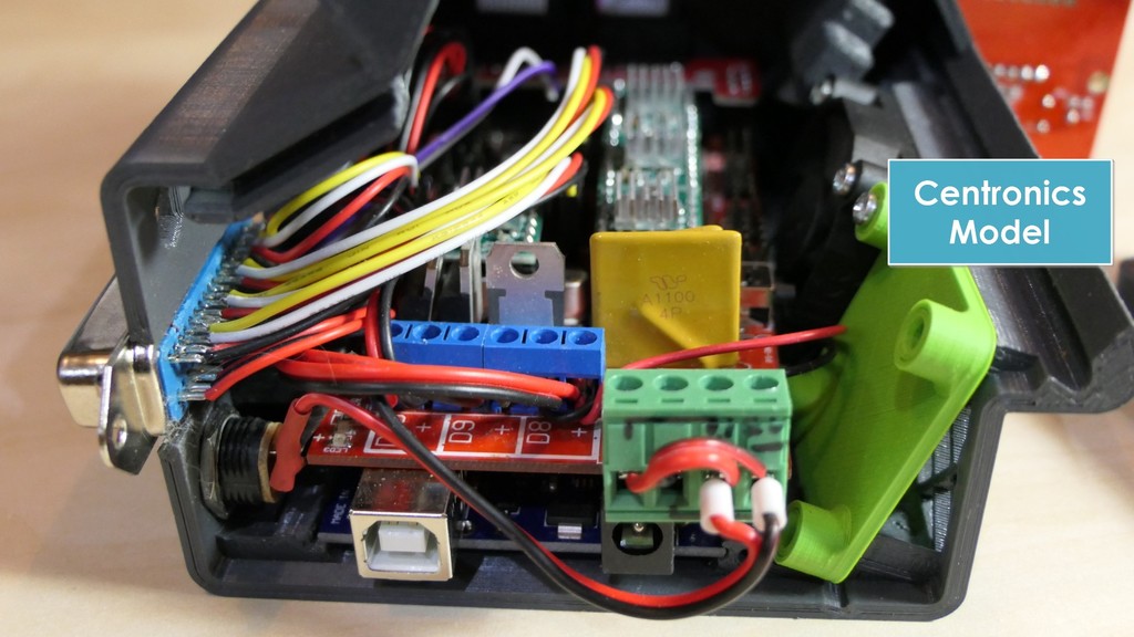
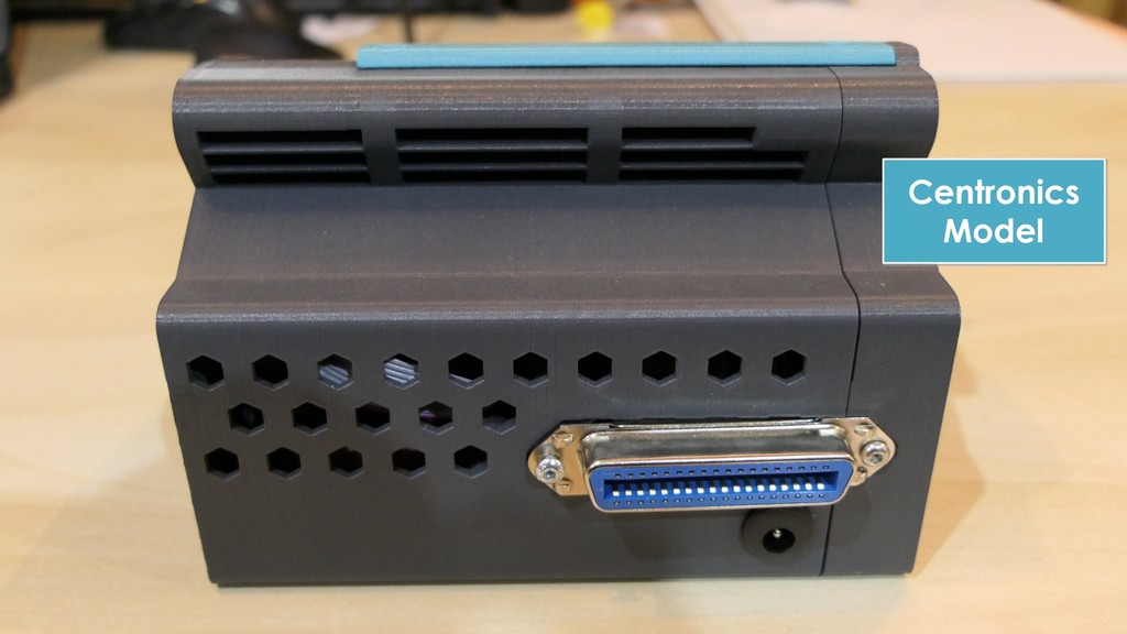
- Une emprunte pour loger un connecteur centronics à 36 broches et permettre un changement de boitier très rapide, en cas de panne par exemple.
- Plus d'espace ! On peut désormais empiler sur la RAMPS des smoothers des drivers et des radiateurs hauts.
- La ventilation du boitier peut être assurée par convection naturelle, ce qui est suffisant par exemple lorsqu'on pilote une delta sans plateau chauffant avec des drivers A4980 bien réglés, mais on peut également installer un ou deux ventilateurs 40x40x10 à l'avant du boitier pour satisfaire des besoins de refroidisselent beaucoup plus importants. Si vous n'utilisez qu'un seul ventilateur, obturez l'emplacement du second avec la pièce
Opturateur_Fan_40x40_avec_plots.stl pour une ventilation optimale.
Versions précédentes du boitier :
- Boitier v3
- Boitier v2
- Boitier v1
##Introduction##
NB : Toutes les pièces sont conçues pour être imprimées sans support matériel.
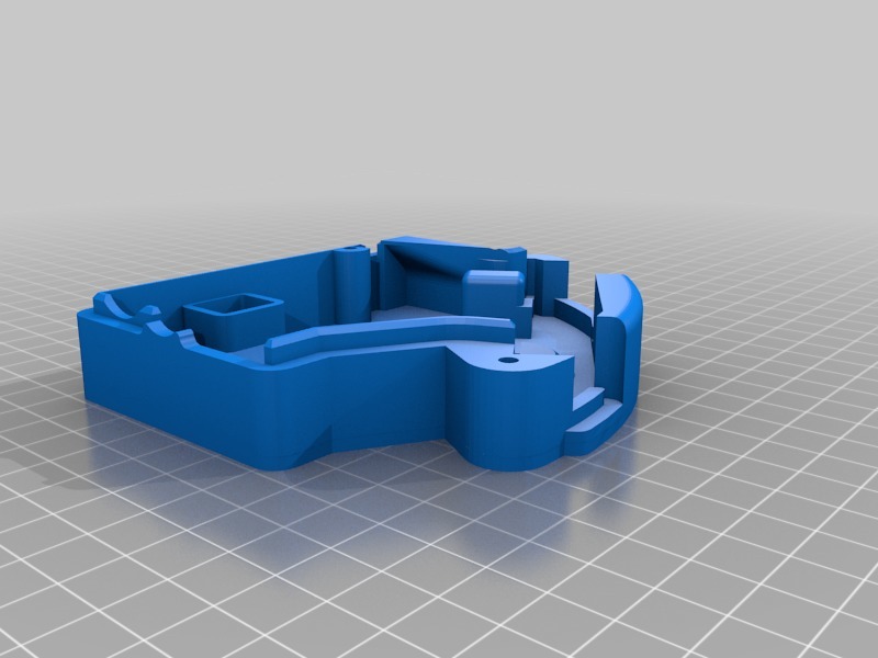
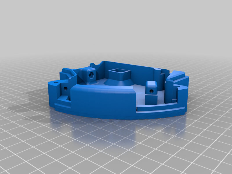
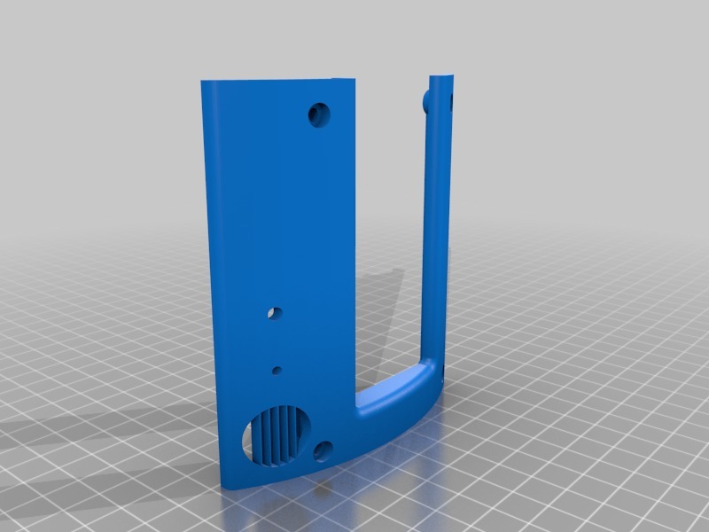
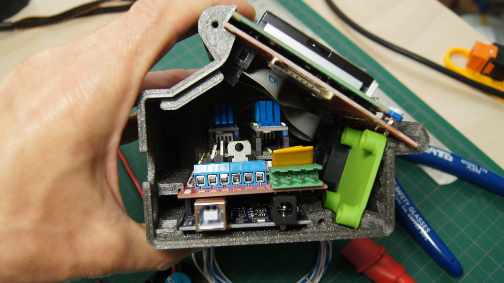
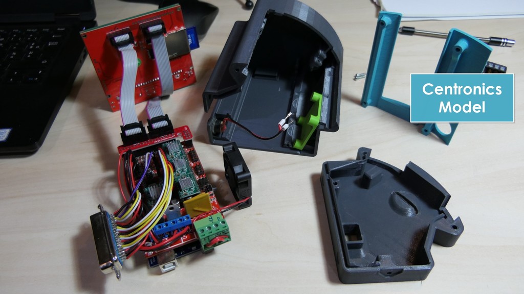
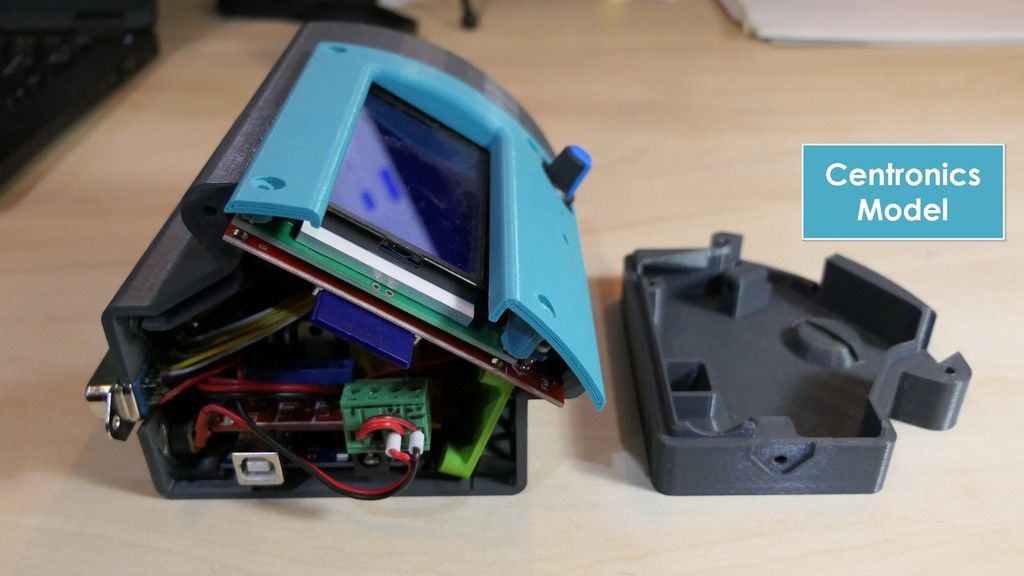
L'assemblage compte trois pièces imprimées :
- le corps principal
- le couvercle latéral
- le capot pour l'écran LCD
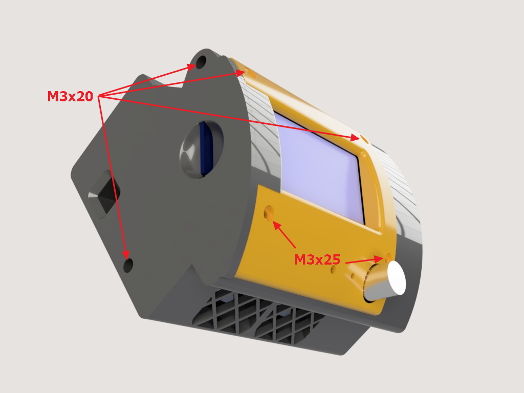
Quincaillerie :
- 4 vis M3x20
- 2 vis M3x25 (ou M3x30)
- 8 vis pour thermoplastique 2,5x12 pour fixer les ventilateurs
- 1 connecteur électrique femelle 2,1x5,5 mm
##Préparation##
- Imprimez et nettoyez les pièces, puis vérifiez que tout s’emboîte correctement
- C'est tout :)
##Câblage##
J'ai réalisé ce boitier pour mon imprimante 3D de type Delta que j'ai conçu pour le nomadisme. Elle doit être en mesure de fonctionner sur un e prise allume-cigare de voiture ou sur des panneaux solaires photovoltaïques. Pour cette raison, elle n'a pas de plateau chauffant et le composant le plus énergivore est la cartouche de chauffe de 40W de la HotEnd.
J'utilise différentes sections de câbles :
- Pour la cartouche de chauffe de 40W de la HotEnd :
Intensité =P/U = 40/12 = 3,34A
Section : S = résistivité du cuivre x longueur de cable (aller plus retour) x Intensité / chute de tension acceptée (3% dans mon cas)
S=0.017x5x3,34/0,36 = 0,79mm2 (AWG18 : 0.823mm2), par sécurité je choisi la valeur directement supérieur AWG17 (1.04mm2).
- Pour les moteurs : Les cables vendus avec les moteurs NEMA 17 sont des 26AWG, je vais donc utiliser cette même section
- Pour tout le reste, la consommation électrique est très faible :
Thermistance : 18mw Max, ou 3.6mA sous 5V
ventilateur 40x40mm : 0.8w sous 12V ou : I = P / U = 0.8 / 12 = 66mA, Si j'en installe deux en parallèle ⇒ 134mA
Mon capteur de nivellement du lit est passif, c'est un simple bouton poussoir, il ne consomme donc rien.
Sachant que la puissance maximum pour un conducteur sera de 134mA, que la longueur maximum des câbles sera de 5m. Il me faudra utiliser un câble de section :
S = 0.017x5x0.134 / 0.36 = 0.032mm2. La section normalisée directement supérieure ou égale est AWG32 = 0.0320mm2 . Si j'utilise un câble de section AWG30 (0.0509mm2) que l'on trouve facilement, le courant max qui pourra le parcourir sous une tension de 12V sera : S = 0.017 x L x I / PT → I = S x PT / (0.017 x L) = 0.0509 x 0.36 / (0.017 x 5) = 0.250 mA (ce qui est largement suffisant)
Un câble Ethernet pourra faire l'affaire, les sections des conducteurs sont généralement comprises entre AWG32 et AWG26, mais attention, d'expérience les câbles trop fins peuvent être fragiles et difficiles à souder.
Dans mon cas, j'utilise un câble Ethernet flexible AWG26 pour câbler tout les composants situés sur l’effecteur, à l'exception de la cartouche de chauffe de la HotEnd.
Avec cette configuration, je n'ai jamais rencontré de problème depuis sa mise en œuvre en 2016 :)
Pour information, j'ai câblé mon connecteur comme ceci :
01 - 04 : A stepper motor
05 - 08 : B stepper motor
09 - 12 : C stepper motor
13 - 16 : Extruder stepper motor
17 - 18 : Cartouche de chauffe HotEnd (D10)
19 - 20 : Fin de course Colonne A (X)
21 - 22 : Fin de course Colonne B (Y)
23 - 24 : Fin de course Colonne C (Z)
25 - 28 : Non utilisés pour l'instant
29 - 30 : Ventilateur ColdEnd (D8) (Câble Ethernet)
31 - 32 : Ventilateur impression (D9) (Câble Ethernet)
33 - 34 : Palpeur de niveau du lit (for autobed leveling) (Câble Ethernet)
35 - 36 : Thermistance HotEnd (T0) (Câble Ethernet)
N'oubliez pas de poster une photo de votre réalisation, ça fait toujours plaisir :)
#English#
Here is the v4 of my case for Arduino MEGA + RAMPS + LCD 12864.
The ventilation can be provided by one or two fans 40x40x10 placed at the front of the case.
Inside are housed:
- One Arduino Mega board
- One RAMPS (1.4 or 1.5 or 1.6)
- One 12864 LCD display
- One or two fan(s) 40x40x10.
This piece is an element of the foldable Delta 3D Printer DeltaFold
##What's new in this v4?##
- Two connection variants :
- A simple hole at the back of the housing for routing all cables
- A print to put a a 36-pin centronics connector and allow a very quick change of case, in case of failure for example.
- More space ! We can now stack on the RAMPS smoothers, drivers and high heat sink.
- Ventilation of the case can be ensured by natural convection, which is sufficient for example when driving a delta printer without heating bed with A4980 drivers well adjusted, but we can also install one or two fans 40x40x10 at the front of the box to satisfy much larger cooling needs. If you only use one fan, close the second slot with the
Fan_Family_40x40_with_plots.stl for an optimal ventilation.
Previous versions of the case :
- Boitier v3
- Boitier v2
- Boitier v1
##Introduction##
NB : All parts are designed to be printed without material support.
The assembly consists of four printed parts :
- the main body
- aside cover
- a cover for the LCD screen
Hardware:
- 4 screw M3x20
- 2 screw M3x25 (or M3x30)
- 1 female electrical connector 2,1x5,5 mm
- 8 screws for thermoplastic 2,5x12 to fix the fans
##Prep##
1. Print and clean the parts, then make sure everything fits properly
2. That all :)
##Wiring##
I made this case for my Delta type 3D printer that I designed for nomadism. It must be able to operate on a car cigarette lighter socket or on voltaic solar panels. For this reason, it does not have a heated bed and the most energy-consuming component is the HotEnd 40W heating cartridge.
I use several cables with different sections :
For the HotEnd 40W heating cartridge :
Intensity =P/U = 40/12 = 3,34A
Section : S = Copper resistivity x Cable length (going and coming) x Intensity / Tension drop accepted (3% in my case)
S=0.017x5x3,34/0,36 = 0,79mm2 (AWG18 : 0.823mm2), for safety i chose AWG17 (1.04mm2).
For the motors : the cables supplied with my NEMA 17 are 26AWG, so i use this section wires
For the rest, the power absorbed by all the other components is very much lower:
Thermistor : 18mw Max, or 3.6mA under 5V
40x40mm fan: 0.8w under 12V or: I = P / U = 0.8 / 12 = 66mA, If i put two of them in parallel ⇒ 134mA
My Auto leveling sensor is a passive push-button so no consumption, only line loss when closed
The max power for a wire will therefore be 134mA, and the max wire length will be 5m.
S = 0.017x5x0.134 / 0.36 = 0.032mm2,
The directly higher normalized section is AWG32 = 0.0320mm2
If I use AWG30 (0.0509mm2) which is easily found, the max current under 12v will be:
S = 0.017 x L x I / PT → I = S x PT / (0.017 x L) = 0.0509 x 0.36 / (0.017 x 5) = 0.250 mA (which is more than enough)
Ethernet cables can do the trick, they generally have conductors whose section varies between AWG32 and AWG26, but with experience, these small cables can be fragile and difficult to solder.
In my case, I use a flexible ethernet cable to wire every component from the case to my effector (except the Hotend cartridge). So, pins 29 to 36 are solder on an AWG26 ethernet cable.
With this configuration, I never encountered any problem since its implementation in 2016 :)
In my case, I'm wiring the Centronics connector like this :
01 - 04 : A stepper motor
05 - 08 : B stepper motor
09 - 12 : C stepper motor
13 - 16 : Extruder stepper motor
17 - 18 : HotEnd cartridge (D10)
19 - 20 : EndStop Column A (X)
21 - 22 : EndStop Column B (Y)
23 - 24 : EndStop Column C (Z)
25 - 28 : spare
29 - 30 : ColdEnd fan (D8)
31 - 32 : Pint fan (D9)
33 - 34 : bed sensor (for autobed leceling)
35 - 36 : HotEnd Thermistot (T0)
Don't forget to post a photo of your realization, it's always nice :)
:format(webp)/https://fbi.cults3d.com/uploaders/12913395/illustration-file/a7fa556a-ed6f-4150-a39d-1af3b10ad043/DSC03159_4_3.jpg)


/https://preview3d-images.cults3d.com/0ci8eg0mnm52loixwnxk6wrtou8e)
/https://preview3d-images.cults3d.com/6te47fsfpo4w7k1abcsikwnd2942)
/https://preview3d-images.cults3d.com/c2amlb9ke7dayt0wf8lov9fqra02)
/https://preview3d-images.cults3d.com/hp82vqae8asdo0u0mk36iz6tply6)
/https://preview3d-images.cults3d.com/dw40i1r0inkl5rpvqgp4v765l117)
/https://preview3d-images.cults3d.com/ais0d80qx1cgqs9l2ma4wcry1sbb)


:format(webp)/https://fbi.cults3d.com/uploaders/12913395/illustration-file/9d97c963-c200-4c1e-9ff1-7e515a42c88c/IMG_20210219_102607_compress67.jpg)
:format(webp)/https://fbi.cults3d.com/uploaders/12913395/illustration-file/868bbcd2-6aae-40ab-a96e-febb9aa17d07/IMG_20210219_175453_compress98.jpg)
:format(webp)/https://fbi.cults3d.com/uploaders/12913395/illustration-file/3c57abf8-a62b-4206-ab82-e09c886ea7f1/IMG_20220522_173633-FullHD.jpg)
:format(webp)/https://fbi.cults3d.com/uploaders/12913395/illustration-file/83c65d00-3afc-4af6-b107-350020db8a73/P1000325_43.jpg)