Flow ratio measuring tool
Flow ratio measuring tool


Print Profile(1)

Description
Sprache/Language: Deutsch + English
A newer version is available: https://makerworld.com/de/models/33073#profileId-29810
Eine neuere Version ist verfügbar: https://makerworld.com/de/models/33073#profileId-29810
English
I have always used the automatic flow rate detection for a filament on my X1 Carbon. However, when the printed parts wouldn't fit together, I questioned the automatic detection. I then manually changed the flow ratio until the parts matched. With experience, this is easy to do, but it also costs time and some material until a satisfactory result is achieved. In Bambu Studio, the flow can also be calibrated manually, but I often could not decide for or against a certain correction value, resulting in a wide range of possible flow rates. However, I only need a value that allows for accurately fitting parts, but the pressure should also be stable. So I designed this tool to read a fitting value after a pressure. The correct flow ratio is then simply calculated from the value with which the print was made.
How does the tool work?
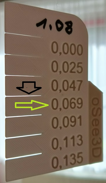
If the flow is set too high, the excess filament is pushed away to the side, the printed strand therefore becomes wider than desired. This leads to thicker walls and parts no longer fit together. The tool is based on this theory. In the photo you can see two arrows. The picture was taken by me in backlight so that the fine differences can be seen.

Visually (or / and also haptically) the first satisfactory interruption is sought. In other words, a gap in the comb that is considered a safe gap (or a safe distance) with a clear conscience. The observation here is from top to bottom, i.e. starting at the value "0.000". The black arrow in the photo points to this line / break. The value on the right below it is then read (the light green arrow points to it). This is the correction value.

The tool is printed with a flow (flow ratio) of 1.08 in the filament settings. Without supports. The model has a chamfer so that it can be easily detached from the print bed. Once the correction value has been read, the calculation is as follows: 1.08 - correction value = new value (flow ratio). So: 1.08 - 0.069 = 1.011
The calculated value can be rounded. If you have some experience with setting the flow ratio, you will be able to interpret the values and the print results of the tool better.
This method and the tool are based on the assumption that the printer should be able to reliably print a distance of 0.1 mm.
This should make it possible to set a flow ratio that is as accurate and reliable as possible.
Have fun printing!
Deutsch
Ich verwendete bei meinem X1 Carbon immer die automatische Erkennung der Flussrate für ein Filament. Nachdem die gedruckten Teile aber einmal nicht ineinander passen wollten, habe ich die automatische Erkennung hinterfragt. Ich habe die Flussrate dann manuell geändert, bis die Teile passten. Mit Erfgahrung ist das ohne Weiteres möglich, kostet doch aber auch Zeit und einiges Material, bis ein zufriedenstellendes Ergebnis erreicht ist. In Bambu Studio kann der Fluss auch manuell kalibriert werden, wobei ich mich aber oft nicht für oder gegen einen bestimmten Korrekturwert entscheiden konnte, was zu einer großen Spanne an möglichen Flussraten führt. Ich brauche aber nur einen Wert, mit dem passgenaue Teile erreicht werden, wobei der Druck aber auch stabil sein soll. So habe ich dieses Werkzeug entworfen, mit dem nach einem Druck ein passender Wert abgelesen werden kann. Aus diesem wird dann einfach das richtige Flussverhältnis (Flussrate) berechnet, aus dem Wert mit dem gedruckt wurde.
Wie funktioniert das Werkzeug?
Ist der Fluss zu hoch eingestellt, wird das überschüssige Filament zur Seite weggedrückt, der gedruckte Strang wird deshalb breiter, als gewünscht. Dies führt zu dickeren Wänden und Teile passen nicht mehr ineinander. Auf dieser Theorie basiert das Werkzeug. Auf dem Foto sind zwei Pfeile zu erkennen. Das Bild wurde von mir im Gegenlicht so fotografiert, dass die feinen Unterschiede zu erkennen sind.

Es wird optisch (oder / und auch haptisch) die erste zufriedenstellende Unterbrechung gesucht. Also ein Abstand im Kamm, der ruhigen Gewissens als sichere Lücke (oder als sicherer Abstand) gilt. Die Betrachtung erfolgt hier von oben nach unten, also bei dem Wert “0,000” beginnend. Der schwarze Pfeil im Foto deutet auf diese Linie / Unterbrechung. Es wird dann der rechts darunterliegende Wert abgelesen (der hellgrüne Pfeil zeigt darauf). Dieses ist der Korrekturwert.

Gedruckt wird das Werkzeug mit einem Fluss (Flussverhältnis) von 1,08 in den Filamenteinstellungen. Ohne Stützen. Das Modell besitzt eine Fase, damit es sich leicht vom Druckbett lösen lässt. Ist der Korrekturwert abgelesen, dann wird wie folgt gerechnet: 1,08 - Korrekturwert = neuer Wert (flow ratio). Also: 1,08 - 0,069 = 1,011
Der berechnete Wert kann gerundet werden. Wenn Sie etwas Erfahrung mit dem Einstellen des Flussverhältnisses haben, werden Sie die Werte und die Druckergebnisse des Werkzeugs besser interpretieren können.
Diese Methode und das Werkzeug basieren auf der Annahme, dass der Drucker einen Abstand von 0,1mm zuverlässig drucken können soll.
So sollte es möglich sein mit einem einzigen Druck ein möglichst genaues Flussverhältnis einzustellen, auf das Verlass ist.
Viel Spaß beim Drucken!
Comment & Rating (6)


License
You shall not share, sub-license, sell, rent, host, transfer, or distribute in any way the digital or 3D printed versions of this object, nor any other derivative work of this object in its digital or physical format (including - but not limited to - remixes of this object, and hosting on other digital platforms). The objects may not be used without permission in any way whatsoever in which you charge money, or collect fees.


