Prints (0)
-
No Prints Yet
Be the first to upload a Print for this Design!
Description
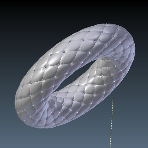
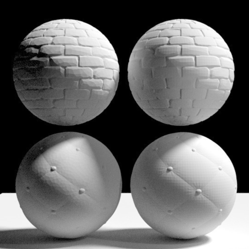
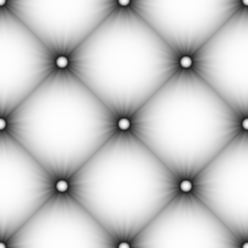
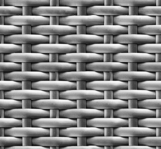
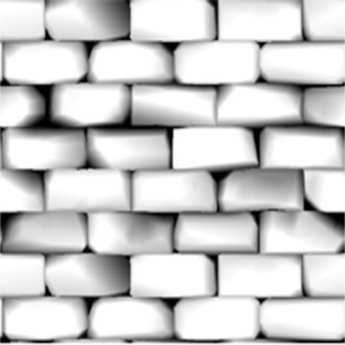
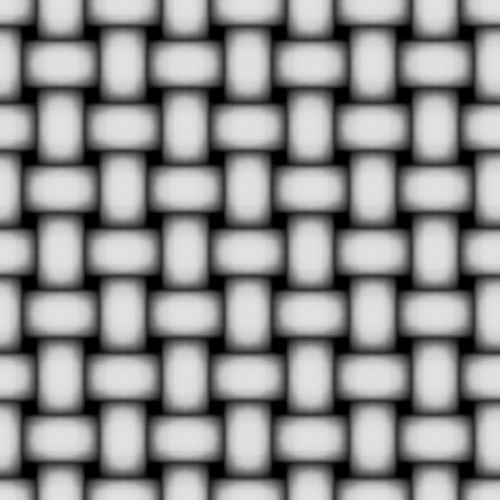
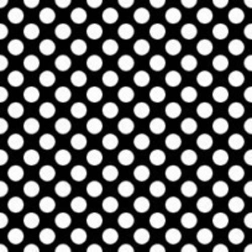
Summary Improved 4K Video version here: https://youtu.be/3Zms6K9LxMQ Go to youtube to view full screen. This project includes Blender files and sample output demonstrating how to use image-based displacement mapping to produce surface textures for 3D printing. When I'm asked how to add surface texture to 3D objects, other than eggs, I always say, "you should use Blender to do it. It's really easy". And it is, once you know your way around Blender. So, as a prerequisite, you'll need Blender 2.78a at least and basic Blender skills. You'll also need to know how to do basic UV texture mapping. There are ton's of videos on You-tube covering this topic, so there is really no need for me to repeat any of that. I'll explain how to use the same basic technique, but for 3d printing. There is a fundamental difference you'll need to understand between texture mapping in 3d graphics, like games, and displacement mapping a 3d mesh like we are doing here for 3d printing. That is, in 3d graphics the surface geometry is not actually displaced when adding texture. The software just modifies the surface normals used to calculate shading at each point on a surface so it looks displaced. So if you look at the profile view, you'll see no points are actually being displaced and the underlying geometry can be very low-res and still look good. But for 3d printing, our task is to actually displace the surface of the mesh in geometry, not just simulation in rendering. This is the key difference in the workflow. The steps are: 1) Create a texture in Blender using your displacement image 2) UV map this texture to your object. You will see it on the surface without displacement. 3) Adjust the texture placement and try to minimize distortion 4) Apply a subsurface modifier on simple setting to increase mesh resolution. You will adjust the number of subdivisions later to make your texture appear clearer 5) Apply a displace modifier. Set to use UV texture coordinates and your UVmap from step 2) 6) You should see your surface displacement appear now. If not, try turning up subdivisions on the subsurface modifier. In some cases, you will need to add two subsurface modifiers to get enough resolution on the mesh to see the texture without pixelation. Adjust the amount of subdivision as necessary. 7) Apply a decimate modifier to reduce the resolution of the mesh. Try a factor of 0.1 to 0.01 to start and see how low you can go with it while maintaining surface detail. 8) Export your object to .stl. You'll need to enable the 3D printing plugin under user-preferences to enable this function. I cover this in detail later. I've attached a few blend files and the output .stl files showing the technique. Note how much more efficient the process works on the icosphere versus the UV sphere. I'm out of time and have to stop now. I'll pick up tomorrow on my blog and update this project. I will intend to post examples showing cube, cylinder, cube, torus and a complex shape. NOTE: If the files seem very slow, turn decimate off in the modifier stack until you need it. Also, turning down the subdivisions will speed everything up in exchange for resolution. Updated DisplacmentMappingCubes.blend to include displacement maps in blend file.
Comments